
Installation Manual
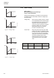
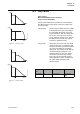
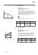
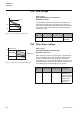
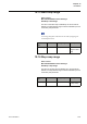
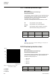
Table Of Contents
- Chapter 1 Introduction
- Chapter 2 Quickstart
- Chapter 3 Description
- Chapter 4 Mounting
- Chapter 5 Connection
- 5:1 General
- 5:2 Electrical connection
- 5:2.1 Main circuit
- 5:2.2 Supply voltage and control circuit
- 5:2.2.1 Supply voltage, terminals 1 and 2
- 5:2.2.2 Earthing, terminal 3
- 5:2.2.3 Start and Stop, terminals 4, 5, 8, 9, 10, 11
- 5:2.2.4 Programmable inputs, terminals 6 and 7
- 5:2.2.5 Programmable output relay K4, terminals 12, 13, and 14
- 5:2.2.6 Programmable output relay K5, terminals 15, 16, and 17
- 5:2.2.7 Programmable output relay K6, terminals 18, 19, and 20
- 5:2.2.8 PTC input
- 5:2.2.9 Analog output
- 5:2.3 Emergency closing of contactor (PSTB370...1050 only)
- 5:3 Connection of communication devices (optional)
- Chapter 6 Human-Machine Interface (HMI)
- Chapter 7 Settings and configuration
- Chapter 8 Fieldbus communication (option)
- Chapter 9 Maintenance
- Chapter 10 Functions
- 10:1 Setting current
- 10:2 Start mode
- 10:3 Stop mode
- 10:4 Tune torque control
- 10:5 Start ramp
- 10:6 Stop ramp
- 10:7 Initial voltage
- 10:8 End voltage
- 10:9 Step down voltage
- 10:10 Current limit
- 10:11 Torque limit
- 10:12 Kick start
- 10:13 Kick start level
- 10:14 Kick start time
- 10:15 Start ramp range
- 10:16 Stop ramp range
- 10:17 Overload protection type
- 10:18 Overload protection class
- 10:19 Overload protection, dual type, start class
- 10:20 Overload protection, dual type, run class
- 10:21 Overload protection, type of operation
- 10:22 Locked rotor protection
- 10:23 Locked rotor protection level
- 10:24 Locked rotor protection time
- 10:25 Locked rotor protection, type of operation
- 10:26 Underload protection
- 10:27 Underload protection level
- 10:28 Underload protection time
- 10:29 Underload protection, type of operation
- 10:30 Phase imbalance protection
- 10:31 Phase imbalance protection level
- 10:32 Phase imbalance protection, type of operation
- 10:33 High current protection
- 10:34 High current protection, type of operation
- 10:35 Phase reversal protection
- 10:36 Phase reversal protection, type of operation
- 10:37 PTC protection
- 10:38 PTC protection, type of operation
- 10:39 External by-pass
- 10:40 High current warning
- 10:41 High current warning level
- 10:42 Low current warning
- 10:43 Low current warning level
- 10:44 Overload warning
- 10:45 Overload warning level
- 10:46 Thyristor (SCR) overload warning
- 10:47 Phase loss fault, type of operation
- 10:48 Fieldbus fault, type of operation
- 10:49 Frequency fault, type of operation
- 10:50 Heat sink over-temperature fault, type of operation
- 10:51 Thyristor short circuit fault, type of operation
- 10:52 By-pass doesn't open fault, type of operation
- 10:53 By-pass doesn't close fault, type of operation
- 10:54 Programmable inputs, In0 and In1
- 10:55 Programmable output relays, K4, K5, and K6
- 10:56 Programmable software output V7
- 10:57 Analog output
- 10:58 Analog output, reference
- 10:59 Analog output, type of value
- 10:60 Analog output, range max
- 10:61 Fieldbus control
- 10:62 Fieldbus type
- 10:63 Fieldbus address
- 10:64 Fieldbus auto disable
- 10:65 Sequence start, number of sequences
- 10:66 Start ramp, first sequence
- 10:67 Initial voltage, first sequence
- 10:68 Current limit, first sequence
- 10:69 Setting current, first sequence
- 10:70 Start ramp, second sequence
- 10:71 Initial voltage, second sequence
- 10:72 Current limit, second sequence
- 10:73 Setting current, second sequence
- 10:74 Start ramp, third sequence
- 10:75 Initial voltage, third sequence
- 10:76 Current limit, third sequence
- 10:77 Setting current, third sequence
- 10:78 Language
- 10:79 LCD automatic switch-off
- 10:80 Password
- 10:81 Date type
- 10:82 Year
- 10:83 Month
- 10:84 Day
- 10:85 Hour
- 10:86 Minutes
- 10:87 Dual current limit time
- 10:88 Dual current limit level
- Chapter 11 Trouble shooting
- Chapter 12 Diagrams
- Chapter 13 Index

Functions
Chapter 10
133
1SFC132003M0201
10:3 Stop mode
Path in menu:
Menu/SETTINGS/Functional Settings/
Torque control/ Stop Mode
Using the PST softstarter it is possible to choose between
two different types of stop ramps. These are voltage ramp
and torque ramp.
Voltage ramp When using the voltage ramp, the voltage
is decreased linearly from full voltage to
the end voltage during stop. Since the
torque depends on both the voltage and
the current, the torque curve does not
always follow the voltage curve. This has
the effect that the torque curve will not
increase or decrease linearly.
Torque ramp When using the torque ramp, the output
voltage to the motor is controlled so that
the torque will follow a predefined optimal
curve from full voltage to end voltage
during stop. This has the benefit that the
mechanical stopping behavior of the
equipment driven by the motor will be
much softer than when using voltage
ramp. This can be especially useful in
pump applications where a sudden stop
can cause water hammering and
pressure surges.
1SFC132162F0001
U
rpm
Stop Time
Stop Time
Figure 3: Voltage ramp
1SFC132163F0001
rpm
U
Stop Time
Stop Time
Figure 4: Torque ramp
Parameter
text
Default value Setting range Description
Stop Mode Volt Volt, Torque Type of stop
ramp