
Installation Manual
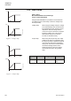
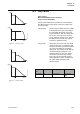
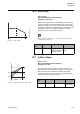
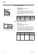
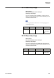
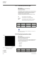
Table Of Contents
- Chapter 1 Introduction
- Chapter 2 Quickstart
- Chapter 3 Description
- Chapter 4 Mounting
- Chapter 5 Connection
- 5:1 General
- 5:2 Electrical connection
- 5:2.1 Main circuit
- 5:2.2 Supply voltage and control circuit
- 5:2.2.1 Supply voltage, terminals 1 and 2
- 5:2.2.2 Earthing, terminal 3
- 5:2.2.3 Start and Stop, terminals 4, 5, 8, 9, 10, 11
- 5:2.2.4 Programmable inputs, terminals 6 and 7
- 5:2.2.5 Programmable output relay K4, terminals 12, 13, and 14
- 5:2.2.6 Programmable output relay K5, terminals 15, 16, and 17
- 5:2.2.7 Programmable output relay K6, terminals 18, 19, and 20
- 5:2.2.8 PTC input
- 5:2.2.9 Analog output
- 5:2.3 Emergency closing of contactor (PSTB370...1050 only)
- 5:3 Connection of communication devices (optional)
- Chapter 6 Human-Machine Interface (HMI)
- Chapter 7 Settings and configuration
- Chapter 8 Fieldbus communication (option)
- Chapter 9 Maintenance
- Chapter 10 Functions
- 10:1 Setting current
- 10:2 Start mode
- 10:3 Stop mode
- 10:4 Tune torque control
- 10:5 Start ramp
- 10:6 Stop ramp
- 10:7 Initial voltage
- 10:8 End voltage
- 10:9 Step down voltage
- 10:10 Current limit
- 10:11 Torque limit
- 10:12 Kick start
- 10:13 Kick start level
- 10:14 Kick start time
- 10:15 Start ramp range
- 10:16 Stop ramp range
- 10:17 Overload protection type
- 10:18 Overload protection class
- 10:19 Overload protection, dual type, start class
- 10:20 Overload protection, dual type, run class
- 10:21 Overload protection, type of operation
- 10:22 Locked rotor protection
- 10:23 Locked rotor protection level
- 10:24 Locked rotor protection time
- 10:25 Locked rotor protection, type of operation
- 10:26 Underload protection
- 10:27 Underload protection level
- 10:28 Underload protection time
- 10:29 Underload protection, type of operation
- 10:30 Phase imbalance protection
- 10:31 Phase imbalance protection level
- 10:32 Phase imbalance protection, type of operation
- 10:33 High current protection
- 10:34 High current protection, type of operation
- 10:35 Phase reversal protection
- 10:36 Phase reversal protection, type of operation
- 10:37 PTC protection
- 10:38 PTC protection, type of operation
- 10:39 External by-pass
- 10:40 High current warning
- 10:41 High current warning level
- 10:42 Low current warning
- 10:43 Low current warning level
- 10:44 Overload warning
- 10:45 Overload warning level
- 10:46 Thyristor (SCR) overload warning
- 10:47 Phase loss fault, type of operation
- 10:48 Fieldbus fault, type of operation
- 10:49 Frequency fault, type of operation
- 10:50 Heat sink over-temperature fault, type of operation
- 10:51 Thyristor short circuit fault, type of operation
- 10:52 By-pass doesn't open fault, type of operation
- 10:53 By-pass doesn't close fault, type of operation
- 10:54 Programmable inputs, In0 and In1
- 10:55 Programmable output relays, K4, K5, and K6
- 10:56 Programmable software output V7
- 10:57 Analog output
- 10:58 Analog output, reference
- 10:59 Analog output, type of value
- 10:60 Analog output, range max
- 10:61 Fieldbus control
- 10:62 Fieldbus type
- 10:63 Fieldbus address
- 10:64 Fieldbus auto disable
- 10:65 Sequence start, number of sequences
- 10:66 Start ramp, first sequence
- 10:67 Initial voltage, first sequence
- 10:68 Current limit, first sequence
- 10:69 Setting current, first sequence
- 10:70 Start ramp, second sequence
- 10:71 Initial voltage, second sequence
- 10:72 Current limit, second sequence
- 10:73 Setting current, second sequence
- 10:74 Start ramp, third sequence
- 10:75 Initial voltage, third sequence
- 10:76 Current limit, third sequence
- 10:77 Setting current, third sequence
- 10:78 Language
- 10:79 LCD automatic switch-off
- 10:80 Password
- 10:81 Date type
- 10:82 Year
- 10:83 Month
- 10:84 Day
- 10:85 Hour
- 10:86 Minutes
- 10:87 Dual current limit time
- 10:88 Dual current limit level
- Chapter 11 Trouble shooting
- Chapter 12 Diagrams
- Chapter 13 Index

Functions
Chapter 10
137
1SFC132003M0201
10:10 Current limit
Path in menu:
Menu/SETTINGS/Functional Settings/
Start/Stop / Current Lim
It is possible to limit the starting current by using this function.
When the current limit is reached, the output voltage stays
stable until the current level falls below the limit, then the
ramping continues.
The starting current must be high enough to make it possible
for the motor to reach the rated speed. The lowest possible
current depends on the performance of the motor and the
characteristics of the load.
10:11 Torque limit
Path in menu:
Menu/SETTINGS/Functional Settings/
Torque control / Torque Limit
It is possible to limit the starting torque by setting this
parameter. When the torque limit is reached, the output
voltage stays stable until the torque falls below the limit, then
the ramping continues.
Torque limit is only available when start mode is set to
torque.
Parameter
text
Default value Setting range Description
Current Lim 4.0 x I
e
2.0...7.0x I
e
Level of the
current limit
U
30%
100%
t1
t2
I
2
5
1SFC132100F0001
F
igure 10: Current limit
FixedF
Time
Time
t1+t2 = set ramp time
Set level of
current limit
Reached set level
of current limit
Fixed voltage
Nm
1SFC132167F0001
Figure 11: Torque limit
Time
Torque
limit
Torque limit reached
Available torque/
Torque during DOL start
Parameter
text
Default value Setting range Description
Torque
Limit
150 % 20...200% Level of the
torque limit
compared to
the nominal
torque of the
motor