
Installation Manual
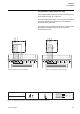
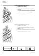
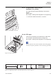
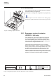
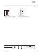
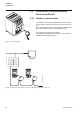

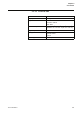

Table Of Contents
- Chapter 1 Introduction
- Chapter 2 Quickstart
- Chapter 3 Description
- Chapter 4 Mounting
- Chapter 5 Connection
- 5:1 General
- 5:2 Electrical connection
- 5:2.1 Main circuit
- 5:2.2 Supply voltage and control circuit
- 5:2.2.1 Supply voltage, terminals 1 and 2
- 5:2.2.2 Earthing, terminal 3
- 5:2.2.3 Start and Stop, terminals 4, 5, 8, 9, 10, 11
- 5:2.2.4 Programmable inputs, terminals 6 and 7
- 5:2.2.5 Programmable output relay K4, terminals 12, 13, and 14
- 5:2.2.6 Programmable output relay K5, terminals 15, 16, and 17
- 5:2.2.7 Programmable output relay K6, terminals 18, 19, and 20
- 5:2.2.8 PTC input
- 5:2.2.9 Analog output
- 5:2.3 Emergency closing of contactor (PSTB370...1050 only)
- 5:3 Connection of communication devices (optional)
- Chapter 6 Human-Machine Interface (HMI)
- Chapter 7 Settings and configuration
- Chapter 8 Fieldbus communication (option)
- Chapter 9 Maintenance
- Chapter 10 Functions
- 10:1 Setting current
- 10:2 Start mode
- 10:3 Stop mode
- 10:4 Tune torque control
- 10:5 Start ramp
- 10:6 Stop ramp
- 10:7 Initial voltage
- 10:8 End voltage
- 10:9 Step down voltage
- 10:10 Current limit
- 10:11 Torque limit
- 10:12 Kick start
- 10:13 Kick start level
- 10:14 Kick start time
- 10:15 Start ramp range
- 10:16 Stop ramp range
- 10:17 Overload protection type
- 10:18 Overload protection class
- 10:19 Overload protection, dual type, start class
- 10:20 Overload protection, dual type, run class
- 10:21 Overload protection, type of operation
- 10:22 Locked rotor protection
- 10:23 Locked rotor protection level
- 10:24 Locked rotor protection time
- 10:25 Locked rotor protection, type of operation
- 10:26 Underload protection
- 10:27 Underload protection level
- 10:28 Underload protection time
- 10:29 Underload protection, type of operation
- 10:30 Phase imbalance protection
- 10:31 Phase imbalance protection level
- 10:32 Phase imbalance protection, type of operation
- 10:33 High current protection
- 10:34 High current protection, type of operation
- 10:35 Phase reversal protection
- 10:36 Phase reversal protection, type of operation
- 10:37 PTC protection
- 10:38 PTC protection, type of operation
- 10:39 External by-pass
- 10:40 High current warning
- 10:41 High current warning level
- 10:42 Low current warning
- 10:43 Low current warning level
- 10:44 Overload warning
- 10:45 Overload warning level
- 10:46 Thyristor (SCR) overload warning
- 10:47 Phase loss fault, type of operation
- 10:48 Fieldbus fault, type of operation
- 10:49 Frequency fault, type of operation
- 10:50 Heat sink over-temperature fault, type of operation
- 10:51 Thyristor short circuit fault, type of operation
- 10:52 By-pass doesn't open fault, type of operation
- 10:53 By-pass doesn't close fault, type of operation
- 10:54 Programmable inputs, In0 and In1
- 10:55 Programmable output relays, K4, K5, and K6
- 10:56 Programmable software output V7
- 10:57 Analog output
- 10:58 Analog output, reference
- 10:59 Analog output, type of value
- 10:60 Analog output, range max
- 10:61 Fieldbus control
- 10:62 Fieldbus type
- 10:63 Fieldbus address
- 10:64 Fieldbus auto disable
- 10:65 Sequence start, number of sequences
- 10:66 Start ramp, first sequence
- 10:67 Initial voltage, first sequence
- 10:68 Current limit, first sequence
- 10:69 Setting current, first sequence
- 10:70 Start ramp, second sequence
- 10:71 Initial voltage, second sequence
- 10:72 Current limit, second sequence
- 10:73 Setting current, second sequence
- 10:74 Start ramp, third sequence
- 10:75 Initial voltage, third sequence
- 10:76 Current limit, third sequence
- 10:77 Setting current, third sequence
- 10:78 Language
- 10:79 LCD automatic switch-off
- 10:80 Password
- 10:81 Date type
- 10:82 Year
- 10:83 Month
- 10:84 Day
- 10:85 Hour
- 10:86 Minutes
- 10:87 Dual current limit time
- 10:88 Dual current limit level
- Chapter 11 Trouble shooting
- Chapter 12 Diagrams
- Chapter 13 Index

Connection
Chapter 5
54
1SFC132003M0201
5:2.2.9 Analog output
If the analog output is used, the cables shall be connected to
terminals 23 and 24, see Figure 30.
See Chapter 7 “Settings and configuration” for programming.
The PTC input uses the same terminals as the Analog output
and only one of these functions can be used at any given time.
5:2.3 Emergency closing of contactor
(PSTB370...1050 only)
If the softstarter for some reason malfunctions (shorted or
non conducting thyristors, burnt PCB etc) it is possible to
close the integrated by-pass contactor and start the motor
using some other starting equipment. Manual closing of the
contactor is done using terminals 30 to 33.
Figure 32 shows how terminals 30 to 33 are connected
during normal operation. If there is a need for an emergency
closing of the contactor, the two bridges between 30, 31 and
32, 33 should be removed and an external power source
should be connected between terminals 31 and 32. See
Figure 33. This will cause the by-pass contactor to close and
it will be possible to start the motor using some other starting
equipment, connected on the line side of the softstarter.
Figure 31: Tightening torques and cable dimensions (1 mm=0.0394 in)
LIS
TED
7F39
IND
. C
ON
T
. EQ
.
1SFA 894 007 R1002
IEC 947-4-2
Ie: 37-72A
Us: 100-250V
AC/DC
UL 508
Uc: 100-250V
AC/DC
FLA: 37-68A
Ma
de
in S
w
eden
Ue: 220-230 380-400 500 V
72: AC-53a: 8-1.6: 80-6
In line 18,5 37
45 kW
Ue 208 220-240 44
0-480
V
In line 20 20
50 Hp
CAUTION
Fuse 250A TYPO
WE
R ZILO
X
Max sh
ort circuit current 65kA at 480V
Wire 1-8 Al C
u 75C
only
, 35lb-in
Overload C
apacity 1
15% of C
ontinuous
Key-Pad
FELDBUSS
1SFC132065F0001
Analogue Output/
PTC
23 24
Figure 30: Analog output connection
M3
1. . . . . . . . . . . . . . . . . . . . . . . . 20
0,5 Nm - 4,3 lb.in
3,5x0,6
0,14 ... 2,5 mm
AWG 12 ... 22
0,14 ... 2,5 mm
2
2
1SFC132053F0001