
Installation Manual


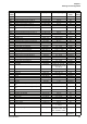
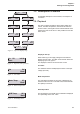

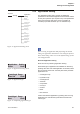
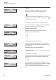
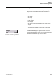
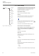
Table Of Contents
- Chapter 1 Introduction
- Chapter 2 Quickstart
- Chapter 3 Description
- Chapter 4 Mounting
- Chapter 5 Connection
- 5:1 General
- 5:2 Electrical connection
- 5:2.1 Main circuit
- 5:2.2 Supply voltage and control circuit
- 5:2.2.1 Supply voltage, terminals 1 and 2
- 5:2.2.2 Earthing, terminal 3
- 5:2.2.3 Start and Stop, terminals 4, 5, 8, 9, 10, 11
- 5:2.2.4 Programmable inputs, terminals 6 and 7
- 5:2.2.5 Programmable output relay K4, terminals 12, 13, and 14
- 5:2.2.6 Programmable output relay K5, terminals 15, 16, and 17
- 5:2.2.7 Programmable output relay K6, terminals 18, 19, and 20
- 5:2.2.8 PTC input
- 5:2.2.9 Analog output
- 5:2.3 Emergency closing of contactor (PSTB370...1050 only)
- 5:3 Connection of communication devices (optional)
- Chapter 6 Human-Machine Interface (HMI)
- Chapter 7 Settings and configuration
- Chapter 8 Fieldbus communication (option)
- Chapter 9 Maintenance
- Chapter 10 Functions
- 10:1 Setting current
- 10:2 Start mode
- 10:3 Stop mode
- 10:4 Tune torque control
- 10:5 Start ramp
- 10:6 Stop ramp
- 10:7 Initial voltage
- 10:8 End voltage
- 10:9 Step down voltage
- 10:10 Current limit
- 10:11 Torque limit
- 10:12 Kick start
- 10:13 Kick start level
- 10:14 Kick start time
- 10:15 Start ramp range
- 10:16 Stop ramp range
- 10:17 Overload protection type
- 10:18 Overload protection class
- 10:19 Overload protection, dual type, start class
- 10:20 Overload protection, dual type, run class
- 10:21 Overload protection, type of operation
- 10:22 Locked rotor protection
- 10:23 Locked rotor protection level
- 10:24 Locked rotor protection time
- 10:25 Locked rotor protection, type of operation
- 10:26 Underload protection
- 10:27 Underload protection level
- 10:28 Underload protection time
- 10:29 Underload protection, type of operation
- 10:30 Phase imbalance protection
- 10:31 Phase imbalance protection level
- 10:32 Phase imbalance protection, type of operation
- 10:33 High current protection
- 10:34 High current protection, type of operation
- 10:35 Phase reversal protection
- 10:36 Phase reversal protection, type of operation
- 10:37 PTC protection
- 10:38 PTC protection, type of operation
- 10:39 External by-pass
- 10:40 High current warning
- 10:41 High current warning level
- 10:42 Low current warning
- 10:43 Low current warning level
- 10:44 Overload warning
- 10:45 Overload warning level
- 10:46 Thyristor (SCR) overload warning
- 10:47 Phase loss fault, type of operation
- 10:48 Fieldbus fault, type of operation
- 10:49 Frequency fault, type of operation
- 10:50 Heat sink over-temperature fault, type of operation
- 10:51 Thyristor short circuit fault, type of operation
- 10:52 By-pass doesn't open fault, type of operation
- 10:53 By-pass doesn't close fault, type of operation
- 10:54 Programmable inputs, In0 and In1
- 10:55 Programmable output relays, K4, K5, and K6
- 10:56 Programmable software output V7
- 10:57 Analog output
- 10:58 Analog output, reference
- 10:59 Analog output, type of value
- 10:60 Analog output, range max
- 10:61 Fieldbus control
- 10:62 Fieldbus type
- 10:63 Fieldbus address
- 10:64 Fieldbus auto disable
- 10:65 Sequence start, number of sequences
- 10:66 Start ramp, first sequence
- 10:67 Initial voltage, first sequence
- 10:68 Current limit, first sequence
- 10:69 Setting current, first sequence
- 10:70 Start ramp, second sequence
- 10:71 Initial voltage, second sequence
- 10:72 Current limit, second sequence
- 10:73 Setting current, second sequence
- 10:74 Start ramp, third sequence
- 10:75 Initial voltage, third sequence
- 10:76 Current limit, third sequence
- 10:77 Setting current, third sequence
- 10:78 Language
- 10:79 LCD automatic switch-off
- 10:80 Password
- 10:81 Date type
- 10:82 Year
- 10:83 Month
- 10:84 Day
- 10:85 Hour
- 10:86 Minutes
- 10:87 Dual current limit time
- 10:88 Dual current limit level
- Chapter 11 Trouble shooting
- Chapter 12 Diagrams
- Chapter 13 Index

Settings and configuration
Chapter 7
86
1SFC132003M0201
Start mode
The start mode of the motor is displayed. The possible
options are:
•Volt
• Torque
Stop mode
The stop mode of the motor is displayed. The possible
options are:
•Volt
• Torque
Status of inputs/outputs
The status of the Programmable inputs and outputs is
displayed with “0” for not activated or “1” for activated. The
figures have following function:
Real time clock
The real time clock shows present date and time.
How to set date, time and display type see “Presentation
Settings” .
Keypad status
Information on whether the keypad is locked or unlocked.
How to operate, see Chapter 6 “Human-Machine Interface
(HMI)” .
Change Password
Menu for changing the password. How to operate, see
Chapter 6 “Human-Machine Interface (HMI)” .
In=0100 Start signal high
In=1000 Stop signal high
In=0010 In0 high
In=0001 In1 high
Out=1000 Relay K4 activated
Out=0100 Relay K5 activated
Out=0010 Relay K6 activated
Out=0001 SW V7 activated
Start Mode Volt
Back
F
igure 6: Start mode
Stop Mode Torque
Back
F
igure 7: Stop mode
In= 0000 Out= 0000
Back
F
igure 8: Input/outputs
2003-02-05 10:33
Back
Figure 9: Real time clock
Keypad is Active
Back
F
igure 10: Keypad status
Change Password
Select Back
F
igure 11: Change Password