
User`s manual

256 Parameter listing and descriptions
ACH550-01 User's Manual
To fulfil this requirement, connect a thermistor (and other similar
components) to the drive’s control terminals using any of these
alternatives:
• Separate the thermistor from live parts of the motor with
double reinforced insulation.
• Protect all circuits connected to the drive’s digital and
analogue inputs. Protect against contact, and insulate from
other low voltage circuits with basic insulation (rated for the
same voltage level as the drive’s main circuit).
• Use an external thermistor relay. The relay insulation must be
rated for the same voltage level as the drive’s main circuit.
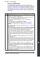
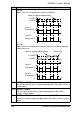
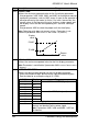
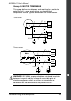
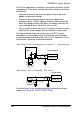
The figures below show thermistor relay and PTC sensor
connections using a digital input. At the motor end, the cable
shield should be earthed through, eg. a 3.3 nF capacitor. If this is
not possible, leave the shield unconnected.
For other faults, or for anticipating motor overheating using a
model, see Group 30: FAULT FUNCTIONS.
Motor
T
Thermistor
relay
Control board
DI
+24 V DC
3501 SENSOR TYPE = 5 (THERM(0)) or 6 (THERM(1)) – Thermistor relay
Motor
T
Control board
DI
+24 V DC
3501 SENSOR TYPE = 5 (THERM(0)) – PTC sensor
3.3 nF