
User`s manual

410 Technical data
ACH550-01 User's Manual
1
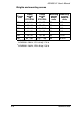
Digital input impedance 1.5 kohm. Maximum voltage for digital
inputs is 30 V.
2
Default values depend on the macro used. Values specified are for
the default macro. See chapter Application macros and wiring.
Note: Terminals 3, 6, and 9 are at the same potential.
Note: For safety reasons the fault relay signals a “fault” when
the ACH550 is powered down.
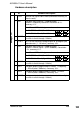
10 +24V Auxiliary voltage output 24 V DC / 250 mA (reference to
GND). Short circuit protected.
11 GND Auxiliary voltage output common (connected internally as
floating).
12 DCOM Digital input common. To activate a digital input, there
must be ≥+10 V (or ≤-10 V) between the input and
DCOM. The 24 V may be provided by the ACH550
(X1:10) or by an external 12…24 V source of either
polarity.
13 DI1 Digital input 1, programmable. Default
2
= start/stop.
14 DI2 Digital input 2, programmable. Default
2
= not used.
15 DI3 Digital input 3, programmable. Default
2
= constant
speed 1 (parameter 1202).
16 DI4 Digital input 4, programmable. Default
2
= Start enable 1
(parameter 1608).
17 DI5 Digital input 5, programmable. Default
2
= not used.
18 DI6 Digital input 6, programmable. Default
2
= not used.
19 RO1C Relay output 1, programmable
Default
2
= Ready
Maximum: 250 V AC / 30 V DC, 2 A
Minimum: 500 mW (12 V, 10 mA)
20 RO1A
21 RO1B
22 RO2C Relay output 2, programmable
Default
2
= Running
Maximum: 250 V AC / 30 V DC, 2 A
Minimum: 500 mW (12 V, 10 mA)
23 RO2A
24 RO2B
25 RO3C Relay output 3, programmable
Default
2
= Fault (-1)
Maximum: 250 V AC / 30 V DC, 2 A
Minimum: 500 mW (12 V, 10 mA)
26 RO3A
27 RO3B
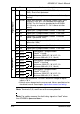
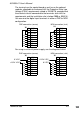
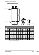
X1 Hardware description
Digital inputs
1
Relay outputs