
Product manual

Installation
Connection of welding equipment
3HEA 801219-002 2005-05 17
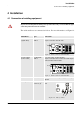
4 Installation
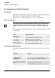
4.1 Connection of welding equipment
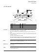
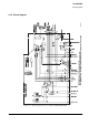
The cables and hoses are connected as follows. For more information, see Figure 12.
All personnel working with the welding robot system must be fully conversant with the appli-
cable safety instructions that are available.
Cable/Hose Type Connection
Feeder cable 1
(signal cable)
A314E/316E/
324E-L
Foot of the robot - Control module
23-pole connection at both ends.
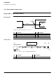
Figure 8. Connection on control module
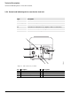
Feeder cable 2
(Power cable)
A314E/316E/
324E-L
Foot of the robot - Control module
12-pole connection at foot of the robot and 19-pole
connection at Control module.
.
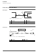
Figure 9. Connection on control module
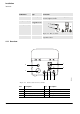
Gas Red hose Connected to the central gas supply or to the gas
cylinder.
Cooling water Blue hose (1)
Red hose (2)
IN
OUT
Figure 10. Wire feed unit
1
2