KV8 Pro AMD AthlonTM 64 System Board Socket 754 User’s Manual 4200-0405-01 Rev. 1.
Copyright and Warranty Notice The information in this document is subject to change without notice and does not represent a commitment on part of the vendor, who assumes no liability or responsibility for any errors that may appear in this manual. No warranty or representation, either expressed or implied, is made with respect to the quality, accuracy or fitness for any particular part of this document.
Table Of Contents Chapter 1. 1-1. 1-2. Chapter 2. 2-1. 2-2. 2-3. 2-4. Hardware Setup.................................................................... 2-1 Install The Motherboard...........................................................................2-1 Install CPU and Heatsink.........................................................................2-2 Install System Memory ............................................................................2-3 Connectors, Headers and Switches ..............
3-10. 3-11. 3-12. Set Password ..........................................................................................3-26 Save & Exit Setup ..................................................................................3-26 Exit Without Saving...............................................................................3-26 Appendix A. Install VIA 4-in-1 Driver ................................................................. A-1 Appendix B. Install Audio Driver ................................
Introduction 1-1 Chapter 1. Introduction 1-1. Features & Specifications 1. CPU • Supports 64-bit AMD AthlonTM 64 processor (Socket 754) • 1600MHz system bus using HyperTransportTM technology 2. CPU Integrated Memory Controller • • • 72-bit memory controller supports DDR at 266, 333 and 400MHz Support 2 DIMM DDR 400 Support 2 DIMM up to 2GB Max. 3.
1-2 Chapter 1 • • 2x USB headers 1x CD-IN, 1x AUX-IN header 9. Back Panel I/O • • • • • • 1x PS/2 keyboard, 1x PS/2 mouse 1x Serial port connector, 1x Parallel port connector 1x S/PDIF In connector 1x S/PDIF Out connector 5 holes Audio connector (Front Speaker, Line-In, Mic-In, Center/Sub, Surround Speaker) 4x USB, 1x RJ-45 LAN Connector 10. Miscellaneous • ATX form factor: 305 x 225 mm Specifications and information contained herein are subject to change without notice.
Introduction 1-3 1-2.
1-4 KV8 Pro Chapter 1
Hardware Setup 2-1 Chapter 2. Hardware Setup Before the Installation: Turn off the power supply switch (fully turn off the +5V standby power), or disconnect the power cord before installing or unplugging any connectors or add-on cards. Failing to do so may cause the motherboard components or add-on cards to malfunction or damaged. 2-1.
2-2 Chapter 2 2-2. Install CPU and Heatsink This motherboard provides a ZIF (Zero Insertion Force) Socket 754 to install AMD Socket 754 CPU. The CPU you bought should contain with a kit of heatsink, cooling fan, retention frame and blackplate. If that’s not the case, buy one specially designed for Socket 754. Please refer to the figure shown here to install CPU and heatsink. (For reference only. Your Heatsink & Fan Assembly may not be exactly the same as this one.) 1.
Hardware Setup 2-3 2-3. Install System Memory This motherboard provides 2 184-pin DDR DIMM slots for memory expansion available from minimum 128MB to maximum 2GB. Table 2-1. Valid Memory Configurations Bank Memory Module Total Memory Bank 0, 1 (DIMM1) 128, 256, 512MB, 1GB 128MB ~ 1GB Bank 2, 3 (DIMM2) 128, 256, 512MB, 1GB 128MB ~ 1GB Total System Memory 128MB ~ 2GB NOTE: No hardware or BIOS setup required after adding or removing memory modules.
2-4 Chapter 2 Power off the computer and unplug the AC power cord before installing or removing memory modules. 1. Locate the DIMM slot on the board. 2. Hold two edges of the DIMM module carefully, keep away of touching its connectors. 3. Align the notch key on the module with the rib on the slot. 4. Firmly press the module into the slots until the ejector tabs at both sides of the slot automatically snaps into the mounting notch.
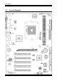
Hardware Setup 2-5 2-4. Connectors, Headers and Switches Here we will show you all of the connectors, headers and switches, and how to connect them. Please read the entire section for necessary information before attempting to finish all the hardware installation inside the computer chassis. A complete enlarged layout diagram is shown in Chapter 1 for all the position of connectors and headers on the board that you may refer to.
2-6 Chapter 2 (2). FAN Connectors These 3-pin connectors each provide power to the cooling fans installed in your system. The CPU must be kept cool by using a powerful fan with heatsink. The system is capable of monitoring the speed of the CPU fan. • CPUFAN1: CPU Fan • NBFAN1: Chipset Fan • SYSFAN1: System Fan • AUXFAN1, AUXFAN2: Auxiliary Fan WARNING: These fan connectors are not jumpers. DO NOT place jumper caps on these connectors.
Hardware Setup 2-7 (3). CMOS Memory Clearing Header This header uses a jumper cap to clear the CMOS memory. • Pin 1-2 shorted (default): Normal operation. • Pin 2-3 shorted: Clear CMOS memory. WARNING: Turn the power off first (including the +5V standby power) before clearing the CMOS memory. Failing to do so may cause your system to work abnormally or malfunction.
2-8 Chapter 2 (4). Wake-up Header These headers use a jumper cap to enable/disable the wake-up function. • USBPWR1: Pin 1-2 shorted (default): Disable wake-up function support at USB1 port. Pin 2-3 shorted: Enable wake-up function support at USB1 port. • USBPWR2: Pin 1-2 shorted (default): Disable wake-up function support at USB2 port. Pin 2-3 shorted: Enable wake-up function support at USB2 port.
Hardware Setup 2-9 (5). Front Panel Switches & Indicators Headers This header is used for connecting switches and LED indicators on the chassis front panel. Watch the power LED pin position and orientation. The mark “+” align to the pin in the figure below stands for positive polarity for the LED connection. Please pay attention to connect these headers. A wrong orientation will only cause the LED not lighting, but a wrong connection of the switches could cause system malfunction.
2-10 Chapter 2 (6). Additional USB Port Headers These headers each provide 2 additional USB 2.0 ports connection through an USB cable designed for USB 2.0 specifications.
Hardware Setup 2-11 (7). Front Panel Audio Connection Header This header provides the connection to audio connector at front panel. • To use the audio connector at front panel, remove all the jumpers on this header, and then connect to front panel by the extension cable provided with the chassis. • To use the audio connector at rear panel, disconnect the extension cable, attach the jumpers back at pin 5-6, and pin 9-10 (default setting). Pin 1 3 5 7 9 11 13 Pin Assignment Audio Mic. Audio Mic.
2-12 (8). Internal Audio Connectors These connectors connect to the audio output of internal CD-ROM drive or add-on card.
Hardware Setup 2-13 (9). Accelerated Graphics Port Slot This slot supports an optional AGP graphics card up to AGP 8X mode. Please refer to our Web site for more information on graphics cards. ATTENTION: This motherboard does not support 3.3V AGP cards. Use only 1.5V or 0.8V AGP cards.
2-14 Chapter 2 (10). Floppy Disk Drive Connector This connector supports two standard floppy disk drives via a 34-pin 34-conductor ribbon cable. Connecting the Floppy Disk Drive Cable: 1. Install one end of the ribbon cable into the FDC1 connector. The colored edge of the ribbon cable should be aligned with pin-1 of FDC1 connector. 2. Install the other end(s) of ribbon cable into the disk drive connector(s). The colored edge of the ribbon cable should be also aligned with pin-1 of disk drive connector.
Hardware Setup 2-15 (11). IDE Connectors This motherboard provides two IDE ports to connect up to four IDE drives at Ultra DMA mode by Ultra ATA/66 ribbon cables. Each cable has 40-pin 80-conductor and three connectors, providing two hard drives connection with motherboard. Connect the single end (blue connector) at the longer length of ribbon cable to the IDE port on motherboard, and the other two ends (gray and black connector) at the shorter length of the ribbon cable to the connectors on hard drives.
2-16 Chapter 2 (12). POST Code Display This is an LED device to display the “POST” Code, the acronym of Power On Self Test. The computer will execute the POST action whenever you power on the computer. The POST process is controlled by the BIOS. It is used to detect the status of the computer’s main components and peripherals. Each POST Code corresponds to different checkpoints that are also defined by the BIOS in advance.
Hardware Setup 2-17 (13). Serial ATA Connectors These connectors are provided to attach one Serial ATA device at each channel via Serial ATA cable.
2-18 Chapter 2 (14). Status Indicators • LED1 (5VSB): This LED lights up when the power supply is connected with power source. • LED2 (VCC): This LED lights up when the system power is on.
Hardware Setup 2-19 (15). System Management Bus Headers This header is reserved for system management bus (SM bus). The SM bus is a specific implementation of an I2C bus. I2C is a multi-master bus, which means that multiple chips can be connected to the same bus and each one can act as a master by initiating a data transfer. If more than one master simultaneously tries to control the bus, an arbitration procedure decides which master gets priority.
2-20 Chapter 2 (16). Back Panel Connectors • Mouse: Connects to PS/2 mouse. • Keyboard: Connects to PS/2 keyboard. • LPT1: Connects to printer or other devices that support this communication protocol. • COM1: Connects to external modem, mouse or other devices that support this communication protocol. • OPTIN1: This connector provides an S/PDIF in connection through optical fiber to digital multimedia devices.
BIOS Setup 3-1 Chapter 3. BIOS Setup This motherboard provides a programmable EEPROM that you can update the BIOS utility. The BIOS (Basic Input/Output System) is a program that deals with the basic level of communication between processor and peripherals. Use the BIOS Setup program only when installing motherboard, reconfiguring system, or prompted to “Run Setup”. This chapter explains the Setup Utility of BIOS utility.
3-2 Chapter 3 F6: You may create a profile to save the new BIOS settings in it. Press button in the main menu, a dialog box with five numbers (1~5) will appear on the screen. Select one number, and press . Then, you will get a confirmation dialog box with a message similar to: Save Profile To BIOS (Y/N)? After pressing “Y”, the following message will appear to assist you in creating a name for the profile. Enter Profile Name: Type the profile name, and press .
BIOS Setup 3-3 3-1. µGuru Utility Brand Name: This item displays the CPU model name, for example: AMD AthlonTM 64 processor 3200+. Frequency: This item displays the processor speed. CPU Operating Speed: This item displays the CPU operating speed according to the type and speed of your CPU. You can also select the [User Define] option to enter the manual option. User Define: WARNING: The wrong settings of the multiplier and external clock in certain circumstances may cause CPU damage.
3-4 Chapter 3 Voltages Control: This option allows you to switch between the default and user-defined voltages. Leave this setting to default unless the current voltage setting cannot be detected or is not correct. The option “User Define” enables you to select the following voltages manually. CPU Core Voltage: This item selects the CPU core voltage. AGP VDDQ Voltage: This item selects the voltage for AGP slot. DDR SDRAM Voltage: This item selects the voltage for DRAM slot.
BIOS Setup 3-5 Back to µGuru Utility Setup Menu: Use <→> key to switch from OC Guru setup menu to ABIT EQ setup menu: ABIT EQ Beep Control: This item allows you to enable or disable ABIT EQ Beep Control function. Temperature Monitoring: Click key to enter its submenu: CPU Temperature/System Temperature/PWM Temperature: These items display the temperature of CPU, System, and Power Module. Shutdown Enable: Use key to enable system shutdown function.
3-6 Chapter 3 Shutdown Temp.: This items sets the temperature that would shutdown the system automatically in order to prevent system overheats. Beep Enable: Use key to enable warning beeps function. Once the system has detected that the CPU/System/PWM’s temperature exceeded the beep temperature limit, warning beeps will sound. Beep Temp.: This item selects the warning temperature limit. NOTE: The shutdown temperature must be set above the warning temperature.
BIOS Setup 3-7 Fan Speed Monitoring: Click key to enter its submenu: CPU/NB/SYS/AUX1/AUX2 FAN Speed: These items display the speed of the fans connected to CPU, NB, SYS, AUX1 and AUX2 FAN headers. Shutdown Enable: Use key to enable system shutdown function. Once the system has detected that the fan speed is lower than the low limit value, system will shutdown automatically. Beep Enable: Use key to enable warning beeps function.
3-8 Chapter 3 FanEQ Control: Click key to enter its submenu: CPU/NB/SYS FanEQ Control: When set to [Enabled], these items allow you to control the CPU/NB/System fan speed by its setting combination of temperature and voltage high/low limit. Reference Temperature: These items display the CPU/NB/System temperature. Control Temp. High/Low: These items set the high and low temperature limit that you want to do the fan speed control.
BIOS Setup 3-9 3-2. Standard CMOS Features This section contains the basic configuration parameters of the BIOS. These parameters include date, hour, VGA card, FDD and HDD settings. Date (mm:dd:yy): This item sets the date you specify (usually the current date) in the format of [Month], [Date], and [Year]. Time (hh:mm:ss): This item sets the time you specify (usually the current time) in the format of [Hour], [Minute], and [Second].
3-10 Chapter 3 IDE Channel 1 Master / Slave, IDE Channel 2 Master / Slave: When set to [Auto], the BIOS will automatically check what kind of IDE drive you are using. If you want to define your own drive by yourself, set it to [Manual] and make sure you fully understand the meaning of the parameters. Please refer to the instruction manual provided by the device’s manufacturer to get the setting right. Access Mode: This item selects the mode to access your IDE devices.
BIOS Setup 3-11 [EGA/VGA]: (Enhanced Graphics Adapter/Video Graphics Array) For EGA, VGA, SVGA and PGA monitor adapters. [CGA 40]: (Color Graphics Adapter) Power up in 40-column mode. [CGA 80]: (Color Graphics Adapter) Power up in 80-column mode. [Mono]: (Monochrome adapter) Includes high-resolution monochrome adapters. Halt On: This item determines whether the system stops if an error is detected during system boot-up. [All Errors]: The system-boot will stop whenever the BIOS detect a non-fatal error.
3-12 Chapter 3 3-3. Advanced BIOS Features Hard Disk Boot Priority: This item selects the hard disks booting priority. By pressing key, you can enter its submenu where the hard disks detected can be selected for the booting sequence to boot up system. This item functions only when there is the option of [Hard Disk] in any one of the First/Second/Third Boot Device items.
BIOS Setup 3-13 [Setup]: The password is required only when accessing the BIOS Setup. [System]: The password is required each time the computer boots up. NOTE: Don’t forget your password. If you forget the password, you will have to open the computer case and clear all information in the CMOS before you can start up the system. But by doing this, you will have to reset all previously set options.
3-14 Chapter 3 3-4. Advanced Chipset Features AGP & P2P Bridge Control: Click key to enter its submenu: AGP Aperture Size: This option specifies the amount of system memory that can be used by the AGP device. The aperture is a portion of the PCI memory address range dedicated for graphics memory address space. AGP 2.0 Mode: This item selects the data transfer rate of AGP device. A higher rate delivers faster and better graphics to your system.
BIOS Setup 3-15 AGP Fast Write: Two options are available: Disabled Enabled. The default setting is Enabled. If your AGP adapter can support this function, then you can choose Enabled. Otherwise, choose Disabled. AGP Master 1 WS Write: Two options are available: Disabled Enabled. The default setting is Disabled. This implements a single delay when writing to the AGP Bus. When you set it to Enabled, two-wait states are used by the system, allowing for greater stability.
3-16 Chapter 3 DRAM Timing Selectable: Two options are available: Manual By SPD. The default setting is By SPD. When set to “By SPD”, the BIOS will read the DRAM module SPD data and automatically set to the values stored in it. DRAM Clock: This item sets the DRAM clock of your DRAM module. The system may be unstable or unable to boot up if your DRAM module does not support the clock you set.
BIOS Setup 3-17 Back to Advanced Chipset Features Setup Menu: LDT & PCI Bus Control: Click key to enter its submenu: Upstream/Downstream LDT Bus Width: This item allows you to select LDT Bus Width. LDT Bus Frequency: This item allows you to select LDT Bus Frequency. PCI1/PCI2 Master 0 WS Write: Two options are available: Enabled or Disabled. The default setting is Enabled.
3-18 Chapter 3 3-5. Integrated Peripherals OnChip IDE Device: Click key to enter its submenu: SATA RAID ROM: This item allows you to use the boot ROM of on-chip Serial ATA RAID to boot-up system. IDE Bus Master: This option enables or disables the IDE bus mastering capability under the DOS environment. Onboard IDE-1/IDE-2 Controller: This item allows you to enable or disable the primary and secondary IDE controller. Select [Disabled] if you want to add a different hard drive controller.
BIOS Setup 3-19 Back to Integrated Peripherals Setup Menu: OnChip PCI Device: Click key to enter its submenu: OnChip Audio Controller: This option enables or disables the audio controller. Onboard LAN Controller: This option enables or disables the LAN controller. LAN Boot ROM: This item enables or disables the Boot ROM on LAN controller. OnChip USB Controller: This option enables or disables the USB controller. USB 2.0 Controller: This option enables or disables the USB 2.
3-20 Chapter 3 Back to Integrated Peripherals Setup Menu: SuperIO Device: Click key to enter its submenu: Onboard FDD Controller: Two options are available: Enabled and Disabled. The default setting is Enabled. You can enable or disable the onboard FDD controller. Onboard Serial Port 1: This is used to specify the I/O address and IRQ of Serial Port 1. Six options are available: Disabled 3F8/IRQ4 2F8/IRQ3 3E8/IRQ4 2E8/IRQ3 AUTO. The default setting is 3F8/IRQ4.
BIOS Setup 3-21 3-6. Power Management Setup ACPI Suspend Type: This item selects the type of Suspend mode. [S1(PowerOn-Suspend)]: Enables the Power On Suspend function. [S3(Suspend-To-RAM)]: Enables the Suspend to RAM function. Run VGABIOS if S3 Resume: Three options are available: Auto Yes No. The default setting is Auto. This item can let you choose when S3 resume active, the VGA BIOS need to be initiative or not. Resume by OnChip USB: Two options are available: Disabled or Enabled.
3-22 Chapter 3 [Power Off]: When power returns after an AC power failure, the system’s power remains off. You must press the Power button to power-on the system. [Power On]: When power returns after an AC power failure, the system’s power will be powered on automatically. [Last State]: When power returns after an AC power failure, the system will return to the state where you left off before power failure occurs.
BIOS Setup 3-23 NOTE: To enable this “Power On” function, the wake-up header of [USBPWR1] and [USBPWR2] must be set to [Enabled] position. Please refer to the configuration of “Wake-up Header” [USBPWR1] and [USBPWR2] in section 2-4, chapter 2. The mouse wake up function can only be used with the PS/2 mouse, not with the COM port or USB type. Some PS/2 mice cannot wake up the system because of compatible problems. If the specs of your keyboard are too old, it may fail to power on.
3-24 Chapter 3 3-7. PnP/PCI Configurations Resources Controlled By: This item configures all of the boot and Plug-and-Play compatible devices. [Auto(ESCD)]: The system will automatically detect the settings. [Manual]: Choose the specific IRQ resources in the “IRQ Resources” menu. IRQ Resources: Click key to enter its submenu: This item sets each system interrupt to either [PCI Device] or [Reserved].
BIOS Setup 3-25 PIRQ_0 Use IRQ No. ~ PIRQ_7 Use IRQ No.: This item specifies the IRQ number manually or automatically for the devices installed on PCI slots.
3-26 Chapter 3 3-8. Load Fail-Safe Defaults This option loads the BIOS default values for the most stable, minimal-performance system operations. 3-9. Load Optimized Defaults This option loads the BIOS default values that are factory settings for optimal-performance system operations. 3-10. Set Password This option protects the BIOS configuration or restricts access to the computer itself. 3-11. Save & Exit Setup This option saves your selections and exits the BIOS setup menu. 3-12.
Install VIA 4-in-1 Driver A-1 Appendix A. Install VIA 4-in-1 Driver NOTE: Please install this VIA 4-in-1 driver first after having installed the Windows operating system. The installation procedures and screen shots in this section are based on Windows XP operating system. For those of other OS, please follow its on-screen instruction. Insert the Driver & Utility CD into CD-ROM drive, it should execute the installation program automatically.
A-2 6. Appendix A Click [Next]. 7. Choose [Yes, I want to restart my computer now.], and click [OK] to complete setup.
Install Audio Driver B-1 Appendix B. Install Audio Driver The installation procedures and screen shots in this section are based on Windows XP operating system. For those of other OS, please follow its on-screen instruction. Insert the Driver & Utility CD into CD-ROM drive, it should execute the installation program automatically. If not, double-click the execution file at the main directory of this CD to enter the installation menu. After entering the installation menu, move your curser to [Drivers] tab.
B-2 KV8 Pro Appendix B
Install LAN Driver C-1 Appendix C. Install LAN Driver To install the LAN driver, please insert the Driver & Utility CD into CD-ROM drive. It should execute the installation program automatically. If not, double-click the execution file at the main directory of this CD to enter the installation menu. The following screen appears. Click [LAN Driver], and then follow the on-screen instruction to complete the driver installation.
C-2 KV8 Pro Appendix C
Install VIA USB 2.0 Driver D-1 Appendix D. Install VIA USB 2.0 Driver NOTE: There is no need to install VIA USB 2.0 driver for the Windows XP operating system with Service Pack 1 already installed. Please run the Windows update for the latest Service Pack. The installation procedures and screen shots in this section are based on Windows 2000 operating system. For those of other OS, please follow its on-screen instruction.
D-2 Appendix D 6. Click [Yes]. 7. Click [OK]. 8. Click [Print to File]. 9. Click [OK].
Install VIA Serial ATA RAID Driver E-1 Appendix E. Install VIA Serial ATA RAID Driver The installation procedures and screen shots in this section are based on Windows XP operating system. For those of other OS, please follow its on-screen instruction. Insert the Driver & Utility CD into CD-ROM drive, it should execute the installation program automatically. If not, double-click the execution file at the main directory of this CD to enter the installation menu.
E-2 6. Choose [Yes, I want to restart my computer now.], and click [Finish] to complete setup. 7. After the system restarted, a shortcut icon appears at the right corner of Windows task bar. KV8 Pro Appendix E 8. This is the “VIA RAID Tool” configuration menu. For more information on how to operate, please refer to the “Help” menu.
Install ABIT µGuru Driver F-1 Appendix F. Install ABIT µGuru Driver ABIT µGuru is a fresh Microprocessor developed by ABIT engineers used only on ABIT motherboards. This processor combines the current ABIT engineered features into a user-friendly Windows-based interface, providing users a perfect environment to maximize PC performance and stability. To install the ABIT µGuru driver, please insert the Driver & Utility CD into CD-ROM drive. It should execute the installation program automatically.
F-2 KV8 Pro Appendix F
POST Code Definition G-1 Appendix G.
G-2 Appendix G 1F 21 23 24 25 26 27 29 2B 2D 33 35 37 39 3C 3E 40 43 47 49 4E 50 52 53 KV8 Pro Load keyboard matrix (notebook platform) HPM initialization (notebook platform) 1. Check validity of RTC value: e.g. a value of 5Ah is an invalid value for RTC minute. 2. Load CMOS settings into BIOS stack. If CMOS checksum fails, use default value instead. Prepare BIOS resource map for PCI & PnP use. If ESCD is valid, take into consideration of the ESCD’s legacy information.
POST Code Definition 55 57 59 5B 5D 60 63 65 67 69 6B 6D 6F 75 76 77 7A 7C 7F G-3 Display number of processors (multi-processor platform) Display PnP logo Early ISA PnP initialization -Assign CSN to every ISA PnP device Initialize the combined Trend Anti-Virus code (Optional Feature) Show message for entering AWDFLASH.EXE from FDD (optional) 1. Initialize Init_Onboard_Super_IO 2. Initialize Init_Onbaord_AUDIO Okay to enter Setup utility; i.e.
G-4 Appendix G 8B 8D 8F 93 94 95 96 FF KV8 Pro 1. Invoke all ISA adapter ROMs 2. Invoke all PCI ROMs (except VGA) 1. Enable/Disable Parity Check according to CMOS setup 2. APM Initialization Clear noise of IRQs Read HDD boot sector information for Trend Anti-Virus code 1. Enable L2 cache 2. Program Daylight Saving 3. Program boot up speed 4. Chipset final initialization. 5. Power management final initialization 6. Clear screen & display summary table 7. Program K6 write allocation 8.
POST Code Definition G-5 AC2003 POST Code Definition: POST (hex) Description Power On Sequence 8.1. 8.2. 8.3. 8.4. 8.5. 8.6. 8.7. 8.8. 8.9. 8.A. 8.B. 8.C. 8.D. 8.D. 8.E. 8.F. 9.0. Start power on sequence Enable ATX power supply ATX power supply ready DDR voltage ready Setup PWM for CPU core voltage Assert PWM for CPU core voltage Check CPU core voltage CPU core voltage ready Initial clock generator IC North Bridge chipset voltage ready AGP voltage ready 3VDUAL voltage ready VDDA 2.
G-6 KV8 Pro Appendix G
Troubleshooting (Need Assistance?) H-1 Appendix H. Troubleshooting (Need Assistance?) Q & A: Q: Do I need to clear the CMOS before I use a new motherboard to assemble my new computer system? A: Yes, we highly recommend that you clear the CMOS before installing a new motherboard. Please move the CMOS jumper from its default 1-2 position to 2-3 for a few seconds, and then back. When you boot up your system for the first time, follow the instructions in the user's manual to load the optimized defaults.
H-2 Appendix H Q: How can I get a quick response to my request for technical support? A: Be sure to follow the guidelines as stated in the “Technical Support Form” section of this manual. If you have a problem during operation, in order to help our technical support personnel quickly determine the problem with your motherboard and give you the answers you need, before filling in the technical support form, eliminate any peripheral that is not related to the problem, and indicate it on the form.
Troubleshooting (Need Assistance?) H-3 Main instructions: To fill in this “Technical Support Form”, refer to the step-by-step instructions given below: 1*. MODEL: Note the model number given in your user’s manual. Example: KV8 Pro * 2 . Motherboard model number (REV): Note the motherboard model number labeled on the motherboard as “REV:*.**”. Example: REV: 1.01 * 3 . BIOS ID and Part Number: See the on screen message. 4.
H-4 Appendix H Technical Support Form Company Name: Phone Number: Contact Person: Fax Number: E-mail Address: Model * Motherboard Model No.
How to Get Technical Support Appendix I. I-1 How to Get Technical Support (From our website) http://www.abit.com.tw (In North America) http://www.abit-usa.com (In Europe) http://www.abit.nl Thank you for choosing ABIT products. ABIT sells all our products through distributors, resellers and system integrators; we have no direct sales to end-users.
I-2 Appendix I 4. Internet Newsgroups. They are a great source of information and many people there can offer help. ABIT's Internet News group, alt.comp.periphs.mainboard.abit, is an ideal forum for the public to exchange information and discuss experiences they have had with ABIT products. Many times you will see that your question has already been asked before. This is a public Internet news group and it is reserved for free discussions. Here is a list of some of the more popular ones: alt.comp.periphs.
How to Get Technical Support I-3 North America and South America: Japan: ABIT Computer (U.S.A.) Corporation 45531 Northport Loop West, Fremont, California 94538, U.S.A. Tel: 1-510-623-0500 Fax: 1-510-623-1092 sales@abit-usa.com technical@abit-usa.com http://www.abit-usa.com ABIT Computer (Japan) Co. Ltd. Fax: 81-3-5396-5110 http://www.abit4u.jp U.K. and Ireland: ABIT Computer (U.K.) Corporation Ltd. Unit 3, 24-26 Boulton Road, Stevenage, Herts SG1 4QX, U.K.
I-4 Appendix I 7. RMA Service. If your system has been working but it just stopped, but you have not installed any new software or hardware recently, it is likely that you have a defective component. Please contact the reseller from whom you bought the product. You should be able to get RMA service there. 8. Reporting Compatibility Problems to ABIT. Because of tremendous number of email messages we receive every day, we are forced to give greater weight to certain types of messages than to others.