KV-85 AMD Athlon 64 System Board Socket 754 User’s Manual Rev. 1.
Copyright and Warranty Notice The information in this document is subject to change without notice and does not represent a commitment on part of the vendor, who assumes no liability or responsibility for any errors that may appear in this manual. No warranty or representation, either expressed or implied, is made with respect to the quality, accuracy or fitness for any particular part of this document.
Table of Contents Chapter 1. 1-1. 1-2. Chapter 2. 2-1. 2-2. 2-3. 2-4. Hardware Setup.................................................................... 2-1 Install The Motherboard...........................................................................2-1 Install CPU, Heatsink and Fan Assembly................................................2-2 Install System Memory ............................................................................2-4 Connectors, Headers and Switches .........................
Chapter 4. 4-1. Driver Installation ................................................................ 4-1 Setup Items...............................................................................................4-2 Appendix A. How to Get Technical Support.............................................
Introduction 1-1 Chapter 1. Introduction 1-1. Features & Specifications 1. CPU • Supports AMD Socket 754 Athlon 64/Sempron Processor with 1600MHz Hyper-Transport • Supports AMD K8 CPU Cool ‘n’ Quiet Technology 2. Memory • 2 x 184-pin DIMM sockets • Supports DDR400/333 Un-buffered ECC/ Non-ECC memory • Supports maximum memory capacity up to 2GB 3. Chipset • VIA K8M800 + VT8237R 4. Graphics • Integrated UniChrome Pro Graphics with 2D/3D/Video controller 5. SATA RAID • Serial ATA 1.
1-2 Chapter 1 9. Back Panel I/O • • • • • • 1x PS/2 keyboard, 1x PS/2 mouse 1x Parallel Port, 1x Serial Port, 1x VGA Connector 4x USB 2.0 Connectors 1x RJ-45 LAN Connector 1x Audio connector (Line-out, Line-in, MIC-in) 10. Miscellaneous • ! mATX form factor: 244 x 244 mm Specifications and information contained herein are subject to change without notice.
Introduction 1-3 1-2.
1-4 KV-85 Chapter 1
Hardware Setup 2-1 Chapter 2. Hardware Setup Before the Installation: Turn off the power supply switch (fully turn off the +5V standby power), or disconnect the power cord before installing or unplugging any connectors or add-on cards. Failing to do so may cause the motherboard components or add-on cards to malfunction or damaged. 2-1.
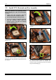
2-2 Chapter 2 2-2. Install CPU, Heatsink and Fan Assembly Please pay attention to the following notices before installing the CPU and heatsink/fan assembly. 1. Always use the processor with the Heatsink and Fan Assembly installed. 2. Do not touch the pins on the processor. 3. If you ever need to reinstall the Heatsink and fan Assembly, please clean the heatsink surface and apply new thermal interface material first. 3. Lower the locking lever to the fully locked position. 1.
Hardware Setup 2-3 6. On the other side, push the retention clip straight down to lock into the plastic lug on the retention frame. 7. Turn the cam lever to lock into the retention frame. 8. Attach the four-pin power plug from the heatsink and fan assembly to the CPU FAN connector. For detailed information on how to install your heatsink and fan assembly, please refer to the instruction manual came packed with the heatsink and fan assembly you bought.
2-4 Chapter 2 2-3. Install System Memory This system board provides two 184-pin DDR DIMM slots for DDR400 memory modules with memory expansion size up to 2GB.
Hardware Setup 2-5 2-4. Connectors, Headers and Switches Here we will show you all of the connectors, headers and switches, and how to connect them. Please read the entire section for necessary information before attempting to finish all the hardware installation inside the computer chassis. A complete enlarged layout diagram is shown in Chapter 1 for all the position of connectors and headers on the board that you may refer to.
2-6 Chapter 2 (2). FAN Connectors These 3-pin connectors each provide power to the cooling fans installed in your system. The CPU must be kept cool by using a powerful fan with heatsink. The system is capable of monitoring the speed of the CPU fan. • CPUFAN1: CPU Fan Power Connector • CASFAN1: Auxiliary Fan Power Connector WARNING: These fan connectors are not jumpers. DO NOT place jumper caps on these connectors.
Hardware Setup 2-7 (3). CMOS Memory Clearing Header This header uses a jumper cap to clear the CMOS memory. • Pin 1-2 shorted (default): Normal operation. • Pin 2-3 shorted: Clear CMOS memory. WARNING: Turn the power off first (including the +5V standby power) before clearing the CMOS memory. Failing to do so may cause your system to work abnormally or malfunction.
2-8 (4). Chapter 2 Front Panel Switches & Indicators Headers These headers are used for connecting switches and LED indicators on the chassis front panel. Watch the power LED pin position and orientation. The mark “+” align to the pin in the figure below stands for positive polarity for the LED connection. Please pay attention to connect these headers. A wrong orientation will only cause the LED not lighting, but a wrong connection of the switches could cause system malfunction.
Hardware Setup 2-9 (5). Additional USB Port Headers These headers each provide 2 additional USB 2.0 ports connection through an USB cable designed for USB 2.0 specifications.
2-10 Chapter 2 (6). Front Panel Audio Connection Header This header provides the connection to audio connector at front panel. • To use the audio connector at front panel, remove all the jumpers on this header, and then connect to front panel by the extension cable provided with the chassis. • To use the audio connector at rear panel, disconnect the extension cable, attach the jumpers back at pin 5-6, and pin 9-10 (default setting). Pin 1 3 5 7 9 KV-85 Pin Assignment Audio Mic. Audio Mic.
Hardware Setup 2-11 (7). Serial ATA Connectors These connectors are provided to attach one Serial ATA device at each channel via Serial ATA cable.
2-12 Chapter 2 (8). Accelerated Graphics Port Slot This slot supports an optional AGP graphics card up to AGP 8X mode. ATTENTION: This motherboard does not support 3.3V AGP cards. Use only 1.5V or 0.8V AGP cards. (9). Internal Audio Connectors These connectors connect to the audio output of internal CD-ROM drive or add-on card.
Hardware Setup 2-13 (10). Floppy and IDE Disk Drive Connectors The FDC1 connector connects up to two floppy drives with a 34-wire, 2-connector floppy cable. Connect the single end at the longer length of ribbon cable to the FDC1 on the board, the two connectors on the other end to the floppy disk drives connector. Generally you need only one floppy disk drive in your system. NOTE: The red line on the ribbon cable must be aligned with pin-1 on both the FDC1 port and the floppy connector.
2-14 Chapter 2 (11). Back Panel Connectors • Mouse: Connects to PS/2 mouse. • Keyboard: Connects to PS/2 keyboard. • LPT1: Connects to printer or other devices that support this communication protocol. • COM1: Connects to external modem, mouse or other devices that support this communication protocol. • VGA1: Connects to monitor input. • LAN: Connects to Local Area Network.
BIOS Setup 3-1 Chapter 3. BIOS Setup This motherboard provides a programmable EEPROM that you can update the BIOS utility. The BIOS (Basic Input/Output System) is a program that deals with the basic level of communication between processor and peripherals. Use the BIOS Setup program only when installing motherboard, reconfiguring system, or prompted to “Run Setup”. This chapter explains the Setup Utility of BIOS utility.
3-2 Chapter 3 In the BIOS Setup main menu, you can see several options. We will explain these options step by step in the following pages of this chapter, but let us first see a short description of the function keys you may use here. Esc: Press this button to quit the BIOS Setup. ↑↓← →: Press these buttons to choose, in the main menu, the option you want to confirm or to modify.
BIOS Setup 3-1. 3-3 Standard CMOS Features This section contains the basic configuration parameters of the BIOS. These parameters include date, hour, VGA card, FDD, and HDD settings. Phoenix – Award WorkstationBIOS CMOS Setup Utility Standard CMOS Features Date (mm:dd:yy) Thu.
3-4 # Chapter 3 IDE Channel 1 Master/Slave, IDE Channel 2 Master/Slave, IDE Channel 3/4 Master: Click key to enter its submenu: Phoenix – Award WorkstationBIOS CMOS Setup Utility IDE Channel 1 Master IDE HDD Auto-Detection Press Enter Item Help IDE Channel 1 Master Access Mode Auto Auto Capacity 0 MB Cylinder Head Precomp Landing Zone Sector 0 0 0 0 0 ↑↓:Move Enter:Select +/-/PU/PD:Value F10:Save ESC:Exit F1:General Help F5: Previous Values F6: Fail-Safe Defaults F7: Optimized Defaults IDE
BIOS Setup 3-5 Head: This item configures the numbers of read/write heads. Precomp: This item displays the number of cylinders at which to change the write timing. Landing Zone: This item displays the number of cylinders specified as the landing zone for the read/write heads. Sector: This item configures the numbers of sectors per track. # Back to Standard CMOS Features Setup Menu: Drive A & Drive B: This item sets the type of floppy drives (usually only Drive A) installed.
3-6 Chapter 3 3-2.
BIOS Setup 3-7 Boot Up Floppy Seek: When set to [Enabled], the BIOS will check whether the floppy disk drive is installed or not. Boot Up NumLock Status: This item determines the default state of the numeric keypad at system booting up. [On]: The numeric keypad functions as number keys. [Off]: The numeric keypad functions as arrow keys. Security Option: This item determines when the system will prompt for password - every time the system boots or only when enters the BIOS setup.
3-8 Chapter 3 3-3.
BIOS Setup ! 3-9 AGP Driving Value: Leave this item to its default setting. AGP Fast Write: Two options are available: Disabled $ Enabled. The default setting is Enabled. If your AGP adapter can support this function, then you can choose Enabled. Otherwise, choose Disabled. AGP Master 1 WS Write: Two options are available: Disabled $ Enabled. The default setting is Disabled. This implements a single delay when writing to the AGP Bus.
3-10 Chapter 3 DRAM Clock (Mhz): This item sets the DRAM clock of your DRAM module. The system may be unstable or unable to boot up if your DRAM module does not support the clock you set. DRAM Command Rate: When the host (northbridge) locates the desired memory address, it then processes the wait state of commands. DRAM CAS# latency Time: You can select SDRAM CAS (Column Address Strobe) latency time according your SDRAM specification.
BIOS Setup 3-11 3-4.
3-12 Chapter 3 IDE Prefetch Mode: Two options are available: Disabled or Enabled. The default setting is Enabled. The onboard IDE drive interfaces supports IDE prefetching for faster drive accesses. If you install a primary and/or secondary add-in IDE interface, set this field to Disabled if the interface does not support prefetching. IDE HDD Block Mode: Enable this filed if your IDE hard drive support block mode.
BIOS Setup ! 3-13 USB Mouse Support via: This item allows you to select [BIOS] for using USB mouse in DOS environment, or [OS] in OS environment.
3-14 ! Chapter 3 Parallel Port Mode: This item specifies the parallel port mode. [SPP]: (Standard Parallel Port) Allows bi-directional parallel port operation at normal speed. [EPP]: (Enhanced Parallel Port) Allows bi-directional parallel port operation at maximum speed. [ECP]: (Extended Capabilities Port) Allows bi-directional parallel port operation at a speed faster than the normal mode’s data transfer rate. [ECP+EPP]: Allows parallel port operation at ECP and EPP mode.
BIOS Setup 3-15 3-5.
3-16 Chapter 3 Wake Up by Ring: When set to [Enabled], any event affecting from Modem Ring will awaken a system that has been powered down. Wake Up by Alarm: When set to [Enabled], you can set the date and time you would like the Soft-Off PC to power-on in the “Date (of Month) Alarm” and “Time (hh:mm:ss) Alarm” items.
BIOS Setup 3-17 3-6. PnP/PCI Configurations Phoenix – Award WorkstationBIOS CMOS Setup Utility PnP/PCI Configurations Resources Controlled By Auto(ESCD) Item Help x IRQ Resources Press Enter PCI/VGA Pallete Snoop Assign IRQ For USB Disbaled Enabled ↑↓:Move Enter:Select +/-/PU/PD:Value F10:Save ESC:Exit F1:General Help F5: Previous Values F6: Fail-Safe Defaults F7: Optimized Defaults Resources Controlled By: This item configures all of the boot and Plug-and-Play compatible devices.
3-18 Chapter 3 PCI/VGA Palette Snoop: This item determines whether the MPEG ISA/VESA VGA cards can work with PCI/VGA or not. [Enabled]: MPEG ISA/VESA VGA cards work with PCI/VGA. [Disabled]: MPEG ISA/VESA VGA cards do not work with PCI/VGA. Assign IRQ For USB: Names the IRQ assigned to the USB on your system. Activity of the selected IRQ always awakens the system.
BIOS Setup 3-19 3-7. PC Health Status Phoenix – AwardBIOS CMOS Setup Utility PC Health Status Shutdown Temperature Disabled CPU Core Voltage DDR Voltage 2.5V ATX +3.3V 3.3V ATX +5V 5.
3-20 Chapter 3 3-8. Load Fail-Safe Defaults This option loads the BIOS default values for the most stable, minimal-performance system operations. 3-9. Load Optimized Defaults This option loads the BIOS default values that are factory settings for optimal-performance system operations. 3-10. Set User Password This option protects the BIOS configuration or restricts access to the computer itself. 3-11. Save & Exit Setup This option saves your selections and exits the BIOS setup menu. 3-12.
Driver Installation 4-1 Chapter 4. Driver Installation All the necessary drivers are included within the Drivers & Utilities CD that came packed with the motherboard. The display shown in the following figure should appear after inserting the Drivers & Utilities CD into your CD-ROM drive, if not, enter $ [My Computer] $ [CD-ROM] Drive $ double click [autorun.exe]. Please follow the on-screen instruction.
4-2 Chapter 4 4-1. Setup Items Drivers: • VIA 4in1 Driver Install the VIA 4-in-1 driver for Windows Operating System. • VIA VGA Driver Install the VIA VGA graphic driver for Windows Operating System. • Audio Driver Install the audio driver for Windows Operating System. • LAN Driver Install the LAN driver for Windows Operating System. • VIA USB 2.0 Driver (1) Install the VIA USB 2.0 driver for Windows 98/ME Operating System. (2) The installation of USB 2.
How to Get Technical Support A-1 Appendix A. How to Get Technical Support (From our website) http://www.abit.com.tw (In North America) http://www.abit-usa.com (In Europe) http://www.abit.nl Thank you for choosing ABIT products. ABIT sells all our products through distributors, resellers and system integrators; we have no direct sales to end-users.
A-2 Appendix A 4. Internet Newsgroups. These are a great source of information and many people there can offer help. ABIT's Internet News group, alt.comp.periphs.mainboard.abit, is an ideal forum for the public to exchange information and discuss experiences they have had with ABIT products. Many times you will see that your question has already been asked before. This is a public Internet news group and it is reserved for free discussions. Here is a list of some of the more popular ones: alt.comp.
How to Get Technical Support North America and South America A-3 ABIT Computer (U.S.A.) Corporation 2901 Bayview Drive Fremont, CA 94538, U.S.A. Tel: 1-510-623-0500 Fax: 1-510-623-1092 Sales: sales@abit-usa.com Latin America Sales: ventas@abit-usa.com Marketing: marketing@abit-usa.com Web Site: http://www.abit-usa.com RMA Center: http://rma.abit-usa.
A-4 Appendix A Poland Japan Taiwan Head Office (Serving all other territories not listed above. Taiwan is 8+ GMT time, and may have different holiday calendar from yours.) ABIT Computer (Poland) Co. Ltd. Przedstawicielstwo w Polsce ul. Wita Stwosza 28, 50-149 Wrocław Tel: 48 71 780 78 65 / 66 Fax: 48 71 372 30 87 Web Site: http://www.abit4u.jp ABIT Computer Corporation No. 323, Yang Guang St., Neihu, Taipei, 114, Taiwan Tel: 886-2-8751-8888 Fax: 886-2-8751-3382 Sales: sales@abit.com.