Motherboard A8N-SLI
E2068 Revised Edition V2 April 2005 Copyright © 2005 ASUSTeK COMPUTER INC. All Rights Reserved. No part of this manual, including the products and software described in it, may be reproduced, transmitted, transcribed, stored in a retrieval system, or translated into any language in any form or by any means, except documentation kept by the purchaser for backup purposes, without the express written permission of ASUSTeK COMPUTER INC. (“ASUS”).
Contents Notices ................................................................................................ vi Safety information ............................................................................. vii A8N-SLI specifications summary ...................................................... viii Chapter 1: Hardware information 1.1 Before you proceed .............................................................. 1-2 1.2 Motherboard overview ..................................................
Contents Chapter 2: 2.1 2.2 2.3 2.4 2.5 2.6 2.7 iv BIOS setup Managing and updating your BIOS ........................................ 2-2 2.1.1 Creating a bootable floppy disk .............................. 2-2 2.1.2 AwardBIOS Flash Utility .......................................... 2-3 2.1.3 ASUS CrashFree BIOS 2 utility ................................ 2-7 BIOS Setup program ............................................................. 2-8 2.2.1 BIOS menu bar .............................
Chapter 3: 3.1 3.2 NVIDIA ® SLI™ technology support NVIDIA® Overview ............................................................................... 3-2 3.1.1 Requirements .......................................................... 3-2 3.1.2 ASUS Certified SLI Graphics cards .......................... 3-2 Dual graphics card setup ...................................................... 3-4 3.2.1 Setting the ASUS EZ selector card ......................... 3-4 3.2.
Notices Federal Communications Commission Statement This device complies with Part 15 of the FCC Rules. Operation is subject to the following two conditions: • This device may not cause harmful interference, and • This device must accept any interference received including interference that may cause undesired operation. This equipment has been tested and found to comply with the limits for a Class B digital device, pursuant to Part 15 of the FCC Rules.
Safety information Electrical safety • To prevent electrical shock hazard, disconnect the power cable from the electrical outlet before relocating the system. • When adding or removing devices to or from the system, ensure that the power cables for the devices are unplugged before the signal cables are connected. If possible, disconnect all power cables from the existing system before you add a device.
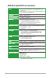
A8N-SLI specifications summary CPU Socket 939 for AMD Athlon™ 64FX/AMD Athlon™ 64 processor Supports AMD 64 architecture that enables simultaneous 32-bit and 64-bit architecture Chipset NVIDIA® nForce™4 SLI Front Side Bus 1 GHz (K8) / 800 MHz Memory Dual-channel memory architecture 4 x 184-pin DIMM sockets support non-ECC unbufferred 400 MHz DDR memory modules Supports up to 2 GB system memory Expansion slots 2 x PCI Express™ x16 slot for discrete graphics cards* 2 x PCI Express™ x1 slots 3 x PCI s
A8N-SLI specifications summary Rear panel 1 x PS/2 mouse port 1 x Parallel port 1 x IEEE 1394a port 1 x LAN (RJ-45) port 4 x USB 2.
x
This chapter lists the hardware setup procedures that you have to perform when installing system components. It includes description of the jumpers and connectors on the motherboard.
1.1 Before you proceed Take note of the following precautions before you install motherboard components or change any motherboard settings. • Unplug the power cord from the wall socket before touching any component. • Use a grounded wrist strap or touch a safely grounded object or a metal object, such as the power supply case, before handling components to avoid damaging them due to static electricity • Hold components by the edges to avoid touching the ICs on them.
1.2 Motherboard overview Before you install the motherboard, study the configuration of your chassis to ensure that the motherboard fits into it. Refer to the chassis documentation before installing the motherboard. Make sure to unplug the power cord before installing or removing the motherboard. Failure to do so can cause you physical injury and damage motherboard components. 1.2.
1.2.3 Motherboard layout 24.5cm (9.6in) PS/2KBMS T: Mouse B: Keyboard CHA2_FAN CPU_FAN ATX12V ALC850 FLOPPY EATXPWR EZ_PLUG PCIEX16_1 PRI_IDE Marvell® 88E1111 SEC_IDE FP_AUDIO Top:Line In Center:Line Out Bottom:Mic In PWR_FAN WARN_LED AUX 30.5cm (12.
1.2.4 Layout contents Slots Page 1. DDR DIMM slots 1-12 2. PCI slots 1-16 3. PCI Express x16 slot 1-16 4. PCI Express x1 slot 1-16 Jumper Page 1. Clear RTC RAM (3-pin CLRTC) 1-17 Rear panel connectors Page 1. PS/2 mouse port 1-18 2. Parallel port 1-18 3. LAN (RJ-45) port 1-18 4. Rear Speaker Out port 1-18 5. Side Spearker Out port 1-18 6. Line In port 1-18 7. Line Out port 1-18 8. Microphone port 1-19 9. Center/Subwoofer port 1-19 10. USB 2.0 ports 3 and 4 1-19 11.
1-6 Internal connectors Page 1. Floppy disk drive connector (34-1 pin FLOPPY1) 1-20 2. Serial port connector (10-1 pin COM1) 1-20 3. IDE connectors (40-1 pin PRI_IDE, SEC_IDE) 1-21 4. Serial ATA connectors (7-pin SATA1, SATA2, SATA3, SATA4) 1-22 5. CPU fan connector (3-pin CPU_FAN) 1-23 6. Chassis fan connectors (3-pin CHA1_FAN, CHA2_FAN) 1-23 7. Chipset fan connector (3-pin CHIP_FAN) 1-23 8. Power fan connector (3-pin PWR_FAN) 1-23 9.
1.3 Central Processing Unit (CPU) The motherboard comes with a surface mount 939-pin Zero Insertion Force (ZIF) socket designed for the AMD Athlon™ 64FX or AMD Athlon™ 64 processor. The 128-bit-wide data paths of these processors can run applications faster than processors with only 32-bit or 64-bit wide data paths. Take note of the marked corner (with gold triangle) on the CPU. This mark should match a specific corner on the socket to ensure correct installation. Gold triangle 1.3.
2. Unlock the socket by pressing the lever sideways, then lift it up to a 90°-100° angle. Socket lever Make sure that the socket lever is lifted up to 90°-100° angle; otherwise the CPU does not fit in completely. 3. Position the CPU above the socket such that the CPU corner with the gold triangle matches the socket corner with a small triangle. 4. Carefully insert the CPU into the socket until it fits in place. Gold triangle Small triangle The CPU fits only in one correct orientation.
1.3.2 Installing the heatsink and fan The AMD Athlon™ 64FX or AMD Athlon™ 64 processor requires a specially designed heatsink and fan assembly to ensure optimum thermal condition and performance. Make sure that you use only qualified heatsink and fan assembly. To install the CPU heatsink and fan: 1. Place the heatsink on top of the installed CPU, making sure that the heatsink fits properly on the retention module base. • The retention module base is already installed on the motherboard upon purchase.
2. Attach one end of the retention bracket to the retention module base. 3. Align the other end of the retention bracket (near the retention bracket lock) to the retention module base. A clicking sound denotes that the retention bracket is in place. Make sure that the fan and heatsink assembly perfectly fits the retention mechanism module base; otherwise, you cannot snap the retention bracket in place. 4.
5. When the fan and heatsink assembly is in place, connect the CPU fan cable to the connector on the motherboard labeled CPU_FAN. GND +12V Rotation CPU_FAN A8N-SLI ® A8N-SLI CPU fan connector Do not forget to connect the CPU fan connector! Hardware monitoring errors can occur if you fail to plug this connector.
1.4 System memory 1.4.1 Overview The motherboard comes with four 184-pin Double Data Rate (DDR) Dual Inline Memory Modules (DIMM) sockets. DIMM_B2 DIMM_B1 DIMM_A2 DIMM_A1 The following figure illustrates the location of the sockets: A8N-SLI ® A8N-SLI 184-pin DDR DIMM sockets 1.4.
1.4.3 Installing a DIMM Make sure to unplug the power supply before adding or removing DIMMs or other system components. Failure to do so may cause severe damage to both the motherboard and the components. 2 1. Unlock a DIMM socket by pressing the retaining clips outward. 2. Align a DIMM on the socket such that the notch on the DIMM matches the break on the socket. DDR DIMM notch 1 1 Unlocked retaining clip A DDR DIMM is keyed with a notch so that it fits in only one direction.
1.5 Expansion slots In the future, you may need to install expansion cards. The following sub-sections describe the slots and the expansion cards that they support. Make sure to unplug the power cord before adding or removing expansion cards. Failure to do so may cause you physical injury and damage motherboard components. 1.5.1 Installing an expansion card To install an expansion card: 1.
Standard interrupt assignments IRQ Priority 0 1 2 4 5 6 7 8 9 10 11 12 13 14 15 Standard Function 1 2 – 12 13 14 15 3 4 5 6 7 8 9 10 System Timer Keyboard Controller Re-direct to IRQ#9 Communications Port (COM1)* IRQ holder for PCI steering* Floppy Disk Controller Printer Port (LPT1)* System CMOS/Real Time Clock IRQ holder for PCI steering* IRQ holder for PCI steering* IRQ holder for PCI steering* PS/2 Compatible Mouse Port* Numeric Data Processor Primary IDE Channel Secondary IDE Channel * These IRQs
1.5.3 PCI slots The PCI slots support cards such as a LAN card, SCSI card, USB card, and other cards that comply with PCI specifications. The figure shows a LAN card installed on a PCI slot. 1.5.4 PCI Express x16 slot This motherboard supports PCI Express x16 graphic cards that comply with the PCI Express specifications. The figure shows a graphics card installed on the PCI Express x16 slot.
1.6 Jumper Clear RTC RAM (CLRTC) This jumper allows you to clear the Real Time Clock (RTC) RAM in CMOS. You can clear the CMOS memory of date, time, and system setup parameters by erasing the CMOS RTC RAM data. The onboard button cell battery powers the RAM data in CMOS, which include system setup information such as system passwords. To erase the RTC RAM: 1. Turn OFF the computer and unplug the power cord. 2. Move the jumper cap from pins 1-2 (default) to pins 2-3.
1.7 Connectors 1.7.1 Rear panel connectors 1 3 2 4 5 6 7 8 15 14 13 12 11 10 9 1. 2. P S / 2 m o u s e p o r t ( g r e e n ) . This port is for a PS/2 mouse. P a r a l l e l p o r t . This 25-pin port connects a parallel printer, a scanner, or other devices. 3. L A N 2 ( R J - 4 5 ) p o r t . Supported by the Marvell® 88E81111 Gigabit LAN controller, this port allows Gigabit connection to a Local Area Network (LAN) through a network hub. LAN port LED indications ACT/LINK LED 4. 5. 6. 7.
8. 9. M i c r o p h o n e p o r t ( p i n k ) . This port connects a microphone. C e n t e r / S u b w o o f e r p o r t ( y e l l o w o r a n g e ) . This port connects the center/subwoofer speakers. Refer to the audio configuration table below for the function of the audio ports in 2, 4, 6, or 8-channel configuration.
1.7.2 1. Internal connectors Floppy disk drive connector (34-1 pin FLOPPY) This connector is for the provided floppy disk drive (FDD) signal cable. Insert one end of the cable to this connector, then connect the other end to the signal connector at the back of the floppy disk drive. The Pin 5 on the connector is removed to prevent incorrect cable connection when using an FDD cable with a covered Pin 5. FLOPPY NOTE: Orient the red markings on the floppy ribbon cable to PIN 1.
3. IDE connectors (40-1 pin PRI_IDE, SEC_IDE) These connectors are for Ultra DMA 133/100/66 signal cables. The Ultra DMA 133/100/66 signal cable has three connectors: a blue connector for the primary IDE connector on the motherboard, a black connector for an Ultra DMA 133/100/66 IDE slave device (optical drive/hard disk drive), and a gray connector for an Ultra DMA 133/ 100/66 IDE master device (hard disk drive).
4. Serial ATA connectors (7-pin SATA1, SATA2, SATA3, SATA4) Supported by the NVIDIA® nForce™4 SLI chipset, these connectors are for the Serial ATA signal cables for Serial ATA hard disk drives that allow up to 3Gb/s of data transfer rate. If you installed Serial ATA hard disk drives, you can create a RAID 0, RAID 1, or RAID 1+0 configuration that span across the Parallel ATA drives.
5. CPU, chassis, power, and chipset fan connectors (3-pin CPU_FAN, 3-pin CHA1_FAN, 3-pin CHA2_FAN, 3-pin PWR_FAN, 3-pin CHIP_FAN)) These fan connectors support cooling fans of 350 mA ~ 2000 mA (24 W max.) or a total of 1 A ~ 3.48 A (41.76 W max.) at +12 V. Connect the fan cable to the fan connector on the motherboard, making sure that the black wire of each cable matches the ground pin of the connector. The chipset fan connector is for the NVIDIA® nForce™4 SLI chipset.
6. USB connectors (10-1 pin USB78, USB56, USB910) These connectors are for USB 2.0 ports. Connect the USB/GAME module cable to any of these connectors, then install the module to a slot opening at the back of the system chassis. These USB connectors comply with USB 2.0 specification that supports up to 480 Mbps connection speed. A8N-SLI USB 2.
8. ATX power connectors (24-pin EATXPWR, 4-pin ATX12V1, 4-pin EZ_PLUG) These connectors are for ATX power supply plugs. The power supply plugs are designed to fit these connectors in only one orientation. Find the proper orientation and push down firmly until the connectors completely fit. • Do not forget to connect the 4-pin ATX +12 V power plug; otherwise, the system will not boot. • Use of a PSU with a higher power output is recommended when configuring a system with more power-consuming devices.
9. Internal audio connectors (4-pin AUX, 4-pin CD) These connectors allow you to receive stereo audio input from sound sources such as a CD-ROM, TV tuner, or MPEG card. A8N-SLI ® AUX (white) Right Audio Channel Ground Ground Left Audio Channel Left Audio Channel Ground Ground Right Audio Channel CD (black) A8N-SLI Internal audio connectors 1 0 .
1 1 . Chassis intrusion connector (4-1 pin CHASSIS) This connector is for a chassis-mounted intrusion detection sensor or switch. Connect one end of the chassis intrusion sensor or switch cable to this connector. The chassis intrusion sensor or switch sends a high-level signal to this connector when a chassis component is removed or replaced. The signal is then generated as a chassis intrusion event.
1 2 . System panel connector (10-1 pin F_PANEL) This connector supports several chassis-mounted functions. PWRSW PLED+ PLEDPWR GND PLED F_PANEL IDE_LED+ IDE_LEDGround Reset NC A8N-SLI ® IDE_LED RESET * Requires an ATX power supply. A8N-SLI System panel connector • System power LED (2-pin PLED) This 3-pin connector is for the system power LED. Connect the chassis power LED cable to this connector.
This chapter tells how to change the system settings through the BIOS Setup menus. Detailed descriptions of the BIOS parameters are also provided.
2.1 Managing and updating your BIOS The following utilities allow you to manage and update the motherboard Basic Input/Output System (BIOS) setup. 1. 2. A w a r d B I O S F l a s h U t i l i t y (Updates the BIOS using a floppy disk during POST.) A S U S C r a s h F r e e B I O S 2 U t i l i t y (Updates the BIOS using a bootable floppy disk when the BIOS gets corrupted.) Refer to the corresponding section for details on these utilities. Important notes 2.1.1 1.
a. Insert a formatted, high density 1.44 MB floppy disk into the drive. b. Insert the Windows® 2000 CD to the optical drive. c. Click S t a r tt, then select R u n n. d. From the Open field, type D:\bootdisk\makeboot a: assuming that D: is your optical drive. e. Press , then follow screen instructions to continue. 2. Copy the original or the latest motherboard BIOS file to the bootable floppy disk. 2.1.
4. When the A : > appears, replace the bootable floppy disk with the floppy disk containing the new BIOS file and the Award BIOS Flash Utility. 5. At the prompt, type a w d f l a s h then press . The Award BIOS Flash Utility screen appears. AwardBIOS Flash Utility for ASUS V1.09 (C) Phoenix Technologies Ltd. All Rights Reserved For NF-KC804-A8N-SLI-00 DATE: 11/30/2004 Flash Type - SST 49LF004A/B /3.3V File Name to Program: Message: Please input File Name! 6.
8. The utility verifies the BIOS file in the floppy disk and starts flashing the BIOS file. AwardBIOS Flash Utility for ASUS V1.09 (C) Phoenix Technologies Ltd. All Rights Reserved For NF-KC804-A8N-SLI-00 DATE: 11/30/2004 Flash Type - SST 49LF004A/B /3.3V File Name to Program: 1001-001.
Saving the current BIOS file You can use the AwardBIOS Flash Utility to save the current BIOS file. You can load the current BIOS file when the BIOS file gets corrupted during the flashing process. To save the current BIOS file using the AwardBIOS Flash Utility: 1. Follow steps 1 to 6 of the previous section. 2. Press when the utility prompts you to save the current BIOS file. The following screen appears. AwardBIOS Flash Utility for ASUS V1.09 (C) Phoenix Technologies Ltd.
2.1.3 ASUS CrashFree BIOS 2 utility The ASUS CrashFree BIOS is an auto recovery tool that allows you to restore the BIOS file when it fails or gets corrupted during the updating process. You can update a corrupted BIOS file using the motherboard support CD or the floppy disk that contains the updated BIOS file. • Prepare the floppy disk containing the updated motherboard BIOS before using this utility. • Make sure that you rename the original or updated BIOS file in the floppy disk to A 8 N - S L I .
2.2 BIOS Setup program This motherboard supports a programmable Flash ROM that you can update using the provided utility described in section “2.1 Managing and updating your BIOS.” Use the BIOS Setup program when you are installing a motherboard, reconfiguring your system, or prompted to “Run Setup.” This section explains how to configure your system using this utility. Even if you are not prompted to use the Setup program, you may want to change the configuration of your computer in the future.
2.2.1 BIOS menu bar The top of the screen has a menu bar with the following selections: MAIN Use this menu to make changes to the basic system configuration. ADVANCED Use this menu to enable and make changes to the advanced features. POWER Use this menu to configure and enable Power Management features. BOOT Use this menu to configure the default system device used to locate and load the Operating System. EXIT Use this menu to exit the current menu or to exit the Setup program.
General help In addition to the Item Specific Help window, the BIOS setup program also provides a General Help screen. You may launch this screen from any menu by simply pressing . The General Help screen lists the legend keys and their corresponding functions. Saving changes and exiting the Setup program See “2.7 Exit Menu” for detailed information on saving changes and exiting the setup program.
2.3 Main Menu When you enter the Setup program, the following screen appears. System Time System Date 17:8:12 Thu, Mar 17 2005 Legacy Diskette A [1.44M, 3.5 in.] Primary IDE Master Primary IDE Slave Secondary IDE Master Secondary IDE Slave First SATA Master Second SATA Master Third SATA Master Fourth SATA Master [ST320410A] [ASUS CD--S520/] [None] [None] [None] [None] [None] [None] Installed Memory 256MB 2.3.1 Select Menu Item Specific Help Change the internal clock.
2.3.5 Primary and Secondary IDE Master/Slave Select Menu Primary IDE Master x Auto Acoustic Management Disabled Primary IDE Master [Auto] Access Mode [Auto] Item Specific Help Press [Enter] to select. Capacity 13579 MB Cylinder 26310 Head 16 Sector 63 PIO Mode [Auto] UDMA Mode [Auto] Transfer Mode UDMA 4 The BIOS automatically detects the values opposite the dimmed items (Capacity, Cylinder, Head, Sector, and Transfer Mode). These values are not user-configurable.
Capacity Displays the auto-detected hard disk capacity. This item is not configurable. Cylinder Shows the number of the hard disk cylinders. This item is not configurable. Head Shows the number of the hard disk read/write heads. This item is not configurable. Sector Shows the number of sectors per track. This item is not configurable. PIO Mode Sets the PIO mode for the IDE device. Configuration options: [Auto] [Mode 0] [Mode 1] [Mode 2] [Mode 3] [Mode 4] UDMA Mode Disables or sets the UDMA mode.
2.3.6 First, Second, Third, and Fourth SATA Master First SATA Master x Auto Acoustic Management Extended IDE Drive Access Mode Select Menu Disabled [Auto] [Auto] Capacity 0 MB Cylinder Head Precomp Landing Zone Sector 0 0 0 0 0 Item Specific Help Sets the type of fixed disk connected to the system. The BIOS automatically detects the values opposite the dimmed items (Capacity, Cylinder, Head, Precomp, Landing Zone and Sector). These values are not user-configurable.
Capacity Displays the auto-detected hard disk capacity. This item is not configurable. Cylinder Shows the number of the hard disk cylinders. This item is not configurable. Head Shows the number of the hard disk read/write heads. This item is not configurable. Precomp Shows the number of precomp per track. This item is not configurable. Landing Zone Shows the number of landing zone per track. This item is not configurable. Sector Shows the number of sectors per track. This item is not configurable.
2.4 Advanced Menu The Advanced menu items allow you to change the settings for the CPU and other system devices. Take caution when changing the settings of the Advanced menu items. Incorrect field values may cause the system to malfunction. CPU Configuration Chipset PCIPnP Onboard Device Configuration SLI Configuration 2-16 Select Menu Item Specific Help Press Enter to set.
2.4.1 CPU configuration The items in this menu show the CPU-related information auto-detected by the BIOS. Select Menu CPU Configuration CPU Type CPU Speed Cache RAM AMD K8 Cool ‘n’ AMD Athlon(tm) 64 Processor 3400+ 2200MHz 512K Quiet control [Enabled] Item Specific Help Enable/Disable Cool`n’Quiet function. AMD K8 Cool ‘n’ Quiet control [Enabled] Enables or disables the AMD K8 Cool `n’ Quiet™ feature.
2.4.2 Chipset configuration The items in this menu show the chipset configuration settings. Select an item then press to display a pop-up menu with the configuration options. Select Menu Chipset DRAM Configuration Errata 94 Enhanced [Press Enter] [Enabled] Item Specific Help DRAM timing and control. DRAM Configuration The items in this sub-menu show the DRAM-related information that the BIOS auto-detects.
Timing Mode [Auto] Sets the timing mode. Configuration options: [Auto] [Manual] Memclock index value [200Mhz] Sets the DRAM frequency. Configuration options: [100Mhz] [133Mhz] [166Mhz] [200Mhz] CAS# latency (Tcl) [2.5] Sets the CAS# latency. Configuration options: [2] [2.5] [3] Min RAS# active time (Tras) [8T] Sets the minimum RAS# active time. Configuration options: [5T] ~ [15T] RAS# to CAS# delay (Trcd) [4T] Sets the RAS# to CAS# delay to Read/Write command on the same bank.
MTRR mapping mode [Continuous] Sets the MTRR mapping mode. Configuration options: [Continuous] [Discrete] Errata 94 Enhanced [Auto] Configuration options: [Auto] [Disabled] 2.4.3 PCIPnP The items in this menu show the PCIPnP configuration settings. Select an item then press to display a pop-up menu with the configuration options.
When the item Resources Controlled By is set to [Auto], the item IRQ Resources is grayed out and is not configurable. Refer to the section “IRQ Resources” for information on how to enable this item. IRQ Resources This sub-menu is activated only when the R e s o u r c e s C o n t r o l l e d B y item is set to Manual.
2.4.4 Onboard device configuration The items in this menu show the onboard device configuration settings. Select an item then press to display a pop-up menu with the configuration options.
IDE Function Setup This sub-menu contains IDE function-related items. Select an item then press to edit.
Serial-ATA 2 [Enabled] Allows you to enable or disable the Serial ATA 2 port. Configuration options: [Disabled] [Enabled] SATA2 DMA transfer [Enabled] Allows you to enable or disable the SATA2 DMA transfer access. Configuration options: [Disabled] [Enabled] IDE Prefetch Mode [Enabled] Allows you to enable or disable the IDE prefetch mode. Configuration options: [Disabled] [Enabled] NVRAID Configuration This sub-menu contains NVRAID function-related items. Select an item then press to edit.
First, Second, Third, Fourth SATA Master RAID [Disabled] Enables or disables the RAID function of the first, second, third or fourth SATA master drive. Configuration options: [Enabled] [Disabled] USB configuration The items in this menu show the USB configuration settings. Select an item then press to display a pop-up menu with the configuration options. USB Configuration USB Controller USB 2.
Onboard LAN [Enabled] Allows you to enable or disable the onboard LAN controller. Keep the default [Enabled] if you wish to use the onboard LAN feature. Set to [Disabled] if you installed a PCI LAN card. Configuration options: [Disabled] [Enabled] Onboard LAN Boot ROM [Disabled] Setting to [Enabled] allowed the BIOS to invoke the boot ROM of the onboard LAN chip. Configuration options: [Enabled] [Disabled] AC97 Audio [Enabled] Allows you to enable or disable the onboard AC`97 Audio controller.
SLI configuration SLI Configuration EZ-Plug Warning [Enabled] Select Menu Item Specific Help EZ-Plug Warning [Enabled] Allows you to enable or disable the EZ-Plug warning feature.
2.5 Power Menu The Power menu allows you to reduce power consumption. This feature turns off the video display and shuts down the hard disk after a period of inactivity. ACPI Suspend Type ACPI APIC Support APM Configuration Hardware Monitor [S3(STR)] [Enabled] Select Menu Item Specific Help Select the ACPI state used for System Suspend. ACPI Suspend Type [S3(STR)] Allows you to select the ACPI state used for system suspend.
2.5.1 APM configuration This menu shows the Advanced Power Management (APM) configuration settings. Select an item then press to display a pop-up menu with the configuration options.
Power-On By Alarm [Disabled] Allows you to enable or disable RTC to generate a wake event. When this item is set to Enabled, the items Date of Month Alarm and Time (hh:mm:ss) Alarm items become user-configurable with set values. Configuration options: [Disabled] [Enabled] The two succeeding items become configurable only when the P o w e r - O n B y R T C A l a r m item is set to [Enabled].
2.5.2 Hardware monitor This menu shows the hardware monitor settings auto-detected by the BIOS. Hardware Monitor Q-Fan Controller Vcore Voltage 3.3V Voltage 5V Voltage 12V Voltage [Enabled] 1.50V 3.31V 4.94V 11.26V CPU Temperature M/B Temperature CPU FAN Speed CHA1 FAN Speed CPU Target Temperature 48ºC 38ºC 4962 RPM 0 RPM [66ºC] Select Menu Item Specific Help Press [Enter] to enable or disable. Q-Fan Controller [Enabled] Allows you to enable or disable the Q-Fan controller.
CPU Target Temperature [66ºC] Allows you to set the CPU temperature threshold. When the CPU temperature reaches the value you set, the CPU fan runs at full speed. Configuration options: [51ºC] [54ºC] [57ºC] [60ºC] [63ºC] [66ºC] [69ºC] [72ºC] [75ºC] [78ºC] [81ºC] This item becomes configurable only when the Q - F a n C o n t r o l l e r item is set to [Enabled]. 2.6 Boot Menu This Boot menu items allow you to change the system boot settings.
2.6.1 Boot Device Priority Boot Device Priority 1st 2nd 3rd 4th Boot Boot Boot Boot Device Device Device Device [CDROM] [Removable] [Hard Disk] [Disabled] Select Menu Item Specific Help Select your boot device priority. 1st ~ xth Boot Device These items specify the boot device priority sequence from the available devices. The number of devices that appears on the screen depends on the number of devices installed in the system.
2.6.3 Boot settings configuration Select Menu Boot Settings Configuration Case Open Warning Quick Boot Boot Up Floppy Seek Bootup Num-Lock OS Select for DRAM > 64MB Full Screen Logo Halt On [Disabled] [Enabled] [Enabled] [On] [Non-OS2] [Enabled] [No Errors] Item Specific Help Press [Enter] to enable or disable. Case Open Warning [Enabled] Enables or disables the chassis open status feature. Setting to Enabled, clears the chassis open status. Refer to section “2.
Full Screen Logo [Enabled] Allows you to enable or disable the full screen logo display feature. Configuration options: [Disabled] [Enabled] Set this item to [Enabled] to use the ASUS MyLogo™ feature. Halt On [No Errors] Sets the system to halt on errors according to the system functions specified in each option.
2.6.4 Security Security Supervisor Password User Password Password Check Select Menu Clear Clear [Setup] Item Specific Help Supervisor password controls full access. to change password. Supervisor Password [Clear] User Password [Clear] These fields allow you to set passwords. To set a password: 1. Highlight an item then press . 2. Type in a password using eight (8) alphanumeric characters, then press . 3.
Forgot the password? If you forget your password, you can clear it by erasing the CMOS Real Time Clock (RTC) RAM. The RAM data containing the password information is powered by the onboard button cell battery. If you need to erase the CMOS RAM, refer to section “1.6 Jumpers” for instructions. Password Check [Setup] This field requires you to enter the password before entering the BIOS setup or the system. Select [Setup] to require the password before entering the BIOS Setup.
Exit & Discard Changes Select this option only if you do not want to save the changes that you made to the Setup program. If you made changes to fields other than system date, system time, and password, the BIOS asks for a confirmation before exiting. Load Setup Defaults This option allows you to load the default values for each of the parameters on the Setup menus. When you select this option or if you press , a confirmation window appears. Select [Yes] to load default values.
This chapter tells how to install SLI-ready PCI Express graphics cards.
3.1 Overview The motherboard supports the NVIDIA® SLI™ (Scalable Link Interface) technology that allows you to install two identical PCI Express™ x16 graphics cards. Follow the installation procedures in this section. 3.1.1 Requirements • You should have two identical SLI-ready graphics cards that are NVIDIA® certified. • Make sure that your graphics card driver supports the NVIDIA SLI technology. Download the latest driver from the NVIDIA website (www.nvidia.com).
GeForce 6800 GT models Vendor Model Number ASUS EN6800GT BFG BFG BFGO68256GTOCX eVGA 256-P2-N376-AX/BX Gigabyte GV-NX68T256DH Leadtek WinFast PX6800 GT XFX/Pine XFX GeForce 6800GT PCI-E (PV-T45G-UD) GeForce 6600 GT models Vendor Model Number Albatron GF6600GT AOpen Aeolus 6600GT-DV128 Asus Extreme N6600GT BFG BFGR6600GTOCX Chaintech SE6600G eVGA 128-P2-N368-AX/BX Gigabyte NX66T128D Leadtek WinFast PX6600GT MSI MS-8983 NX6600GT-VTD128E/NX6600GT-TD128E Palit GeForce 6600GT
3.2 Dual graphics card setup 3.2.1 Setting the ASUS EZ selector card Your motherboard package comes with a preinstalled ASUS EZ selector card. By default, the card is set for a single graphics card. To use two graphics cards on this motherboard, you must first set the selector card to D u a l V i d e o C a r d ss. ASUS EZ selector card To set the selector card: 1. Locate the selector card on the motherboard. Pre-installed ASUS EZ selector card 2.
3. When released, pull the selector card out of the slot. 4. Invert the selector card and insert the edge labeled D u a l V i d e o C a r d ss. 5. Push down the selector card until the retention clips snap into place. Make sure to completely insert the selector card into the slot.
3.2.2 Installing SLI-ready graphics cards Install only identical SLI-ready graphics cards that are NVIDIA® certified. Different types of graphics cards will not work together properly. To install the graphics cards: 1. Prepare two graphics cards. Each graphics card should have goldfingers for the SLI connector. Goldfingers 2. 3-6 Remove the metal bracket covers opposite the two PCI Express x16 slots.
3. Insert one graphics card into the blue slot labeled P C I E X 1 6 _ 1 1. Make sure that the card is properly seated on the slot. 4. Insert the second graphics card into the black slot labeled 2. Make sure that the card is properly seated on the slot. PCIEX16_2 If required, connect an auxiliary power source to the PCI Express graphics cards.
5. Align and insert the SLI connector to the goldfingers on each graphics card. Make sure that the connector is firmly in place. SLI connector 6. Connect a 4-pin ATX power cable to the EZ Plug™ labeled E Z _ P L U G on your motherboard. Make sure to connect a 4-pin ATX power cable to the EZ Plug; otherwise, the system will be unstable. ASUS EZ Plug™ The onboard red warning LED lights up if you do not plug a 4-pin ATX power cable to the EZ Plug.
7. Remove any of the two bracket covers between the graphics cards. Bracket slot 8. Align and insert the retention bracket into the slot then secure it with a screw. Make sure that the retention bracket firmly supports the two graphics cards. Retention bracket 9. Connect a V G A c a b l e or a D V I - I c a b l e to the graphics card installed on the b l u e PCI Express slot.
3.2.3 Installing the device drivers Refer to the documentation that came with your graphics card package to install the device drivers. Make sure that your PCI Express graphics card driver supports the NVIDIA SLI technology. Download the latest driver from the NVIDIA website (www.nvidia.com). 3.2.4 Enabling the multi-GPU feature in Windows® After installing your graphics cards and the device drivers, enable the Multi-Graphics Processing Unit (GPU) feature in the NVIDIA nView properties.
3. 4. From the nView Desktop Manager window, select the D e s k t o p M a n a g e m e n t tab. Click P r o p e r t i e s to display the Display Properties dialog box. 5. From the Display Properties dialog box, select the S e t t i n g s tab then click A d v a n c e d d. 6. Select the N V I D I A G e F o r c e tab.
7. Click the slider to display the following screen, then select the S L I m u l t i - G P U item. Slider 8. 9. 3-12 Click the E n a b l e S L I m u l t i - G P U check box. Click O K when done.