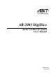
AB-2003 DigiDice Socket 478 Mini PC System User’s Manual 4200-0382-24 Rev. 1.
Copyright and Warranty Notice The information in this document is subject to change without notice and does not represent a commitment on part of the vendor, who assumes no liability or responsibility for any errors that may appear in this manual. No warranty or representation, either expressed or implied, is made with respect to the quality, accuracy or fitness for any particular part of this document.
Safety Instructions 1. Please read these safety instructions carefully. 2. Please keep this User’s Manual for later reference. 3. Please disconnect this equipment from AC outlet before cleaning or inserting any add-on card or module. 4. Don’t use liquid or sprayed detergent for cleaning. Use moisture sheet or cloth for cleaning. 5. Please keep this equipment away from humidity. 6. Lay this equipment on a reliable surface when install. A drop or fall could cause injury. 7.
AB-2003 DigiDice
Table Of Contents Chapter 1. 1.1. 1.2. 1.3. 1.4. 1.5. 1.6. 1.7. 1.8. 1.9. 1.10. 1.11. Chapter 2. 2.1. 2.2. Introduction .................................................... 1-1 Overview............................................................................................1-1 Features..............................................................................................1-1 Installation Notice..............................................................................1-2 Specifications........
2.2.13. Chapter 3. 3.1. 3.2. 3.3. 3.4. 3.5. 3.6. 3.7. 3.8. 3.9. Hardware Setup.............................................. 3-1 Precautions.........................................................................................3-1 Remove The Chassis Cover...............................................................3-2 Install The Memory Module ..............................................................3-4 Install the CPU and Thermal Module ................................................
Chapter 6. 6.1. 6.2. 6.3. 6.4. 6.5. 6.6. 6.7. Exercising Your DigiDice .............................. 6-1 Prior To Powering On The System....................................................6-1 Easy OC (Over Clocking) Setting .....................................................6-2 Powering On The System ..................................................................6-4 Hot Key Controlling ..........................................................................6-5 ABIT EQ and ABIT Manager .............
AB-2003 DigiDice
Introduction Chapter 1. 1-1 Introduction 1.1. Overview DigiDice is a mainstream P4 platform mini pc barebone with superior over-clocking ability & optional RAID function in a small case which provides a 6-in-1Card Reader function, two external 5.25” device bays and two internal 3.5” device bays for ultimate flexibility. In addition, the front LCD display offers useful system information, and the Hot Key design makes the system user-friendlier for specific PC functions.
1-2 Chapter 1 EZ OC (Over Clocking) Setting Two different ways of Over Clocking your system are available. You can either go with 5-level automatic OC (EZ OC) by using knob controller in the front panel, or with ABIT’s exclusive SoftMenu BIOS setting. ABIT EQ System status can be monitored both through the LCD screen on front panel, and the “ABIT EQ” software-based application. Remote Control A handy remote controller is also bundled in the package. You can control and launch programs from distance. 1.
Introduction 1-3 1.4.
1-4 Chapter 1 • • • 1x LCD display 4x Hot-keys 1x Knob button Back Panel I/O • • • • 1x PS/2 Keyboard, 1x PS/2 Mouse 1x VGA Out connector 1x Audio connector (Speaker, Line-out, Line-in, Mic-in, Center/Sub-woofer and SPDIF Out connector) 2x USB 2.0 Connectors, 1x RJ-45 LAN Connector Chassis Material • Aluminum Bezel Color • Silver Bundle Software • • InterVideo WinDVD InterVideo WinRip with MP3 encoder Dimension • 307 x 215 x 255mm (W x H x D) with foot stand Drive Bays • • 2x 5.
Introduction 1-5 1.5.
1-6 Chapter 1 Carrying Bag (bonus parts for deluxe version) 1 Essential Oil (bonus parts for deluxe version) 1 Essential Oil Tank (bonus parts for deluxe version) 1 Remote Controller (bonus parts for deluxe version) 1 AB-2003 DigiDice
Introduction 1-7 1.6. Front Panel 1. Hot Keys 6. Knob Controller 2. LCD Screen 7. Microphone Jack 3. IR Receiver Sensor 8. Headphone Jack 4. Card Reader Slot 9. USB 2.0 Connector 5. 5.25” Empty Tray (For Optical Drive) 10.
1-8 Chapter 1 1.7. Rear Panel 1. AC Power Cord Connector 6. 5.1 Audio Connector 2. PS/2 Keyboard Connector 7. USB 2.0 Connector 3. PS/2 Mouse Connector 8. LAN Connector 4. VGA Out Connector 9. I/O Shield for AGP Slot 5. S/PDIF Out Connector 10.
Introduction 1-9 1.8. Function Keys There are four Hot Keys and one Knob Controller on the front panel. Each button is provided with its multi control function. An infrared receiver sensor is also equipped for a remote convenience.
1-10 Chapter 1 1.9. Dual Optical Drive Bays Two 5.25-inch empty bays at the front panel are available for installing two optical drives. Dust Cover: The disk plate of your optical drive will be ejected through this cover plate after pressing the eject button. Eject Button: Press this button to eject the optical drive.
Introduction 1-11 1.10.
1-12 Chapter 1 1.11. Remote Controller This mini PC is equipped with a remote controller, supporting the control function of WinDVD, WinRip, and Photo Review from distance. This easy control grants you an easy-to-reach AV entertainment. This remote controller is powered by two AAA-size batteries. Point the infrared transmitter of the remote controller to the infrared receiver sensor on the front panel when accessing a remote command.
Introduction 1-13 1.11.1.
1-14 Chapter 1 1.11.2.
Introduction 1-15 1.11.3.
1-16 AB-2003 DigiDice Chapter 1
Knowing Your Motherboard Chapter 2. 2-1 Knowing Your Motherboard 2.1.
2-2 Chapter 2 2.2. Connectors, Headers and Switches WARNING: Always power off the computer and unplug the AC power cord before adding or removing any peripheral or component. Failing to so may cause severe damage to your motherboard and/or peripherals. Plug in the AC power cord only after you have carefully checked everything. 2.2.1. ATX Power Input Connectors Connects to ATX power supply.
Knowing Your Motherboard 2.2.2. 2-3 FAN Connectors These 3-pin connectors each provide power to the cooling fans installed in your system. The CPU must be kept cool by using a powerful fan with heatsink. The system is capable of monitoring the speed of the CPU fan. • CPUFAN1: CPU Fan • SYSFAN1: System Fan • AUXFAN1: Auxiliary Fan • NBFAN1: N.B. Chipset Fan WARNING: These fan connectors are not jumpers. DO NOT place jumper caps on these connectors.
2-4 2.2.3. Chapter 2 CMOS Memory Clearing Header This header uses a jumper cap to clear the CMOS memory. • Pin 1-2 shorted (default): Normal operation. • Pin 2-3 shorted: Clear CMOS memory. ATTENTION: Turn the system power off first (including the +5V standby power) before clearing the CMOS memory. Failing to do so may cause your system to work abnormally or malfunction.
Knowing Your Motherboard 2.2.4. 2-5 Accelerated Graphics Port Slot This slot allows you to connect monitor through an optional AGP card instead of the onboard VGA Out Connector. ATTENTION: This motherboard does not support 3.3V AGP cards. Use only 1.5V or 0.8V AGP cards.
2-6 2.2.5. Chapter 2 PCI Slot The PCI slot allows you to insert PCI card or TV Tuner card.
Knowing Your Motherboard 2.2.6. 2-7 Front Panel Switches & Indicators Connection Headers These headers are used for connecting switches and LED indicators on the chassis front panel. The mark “+” align to the pin in the figure below stands for positive polarity for the LED connection. • HLED (Pin 1, 3): Connects to the HDD LED cable of chassis front panel. • RST (Pin 5, 7): Connects to the Reset Switch cable of chassis front panel.
2-8 Chapter 2 • PWR-ON (Pin 6, 8): Connects to the Power Switch cable of chassis front panel. • PLED (Pin 16, 18, 20): Connects to the Power LED cable of chassis front panel.
Knowing Your Motherboard 2.2.7. 2-9 Additional USB Port Connection Header This header provides 2 additional USB 2.0 ports connection through an USB cable designed for USB 2.0 specifications.
2-10 2.2.8. Chapter 2 LCM1 Connector This connector connects to the LM-01 controller board located inside front panel.
Knowing Your Motherboard 2.2.9. 2-11 Internal Audio Source Connectors These connectors connect to the audio output of internal CD-ROM drive or add-on card.
2-12 Chapter 2 2.2.10. IDE Disk Drive Connectors These IDE ports each connects up to two IDE drives at Ultra ATA/100 mode by one 40-pin, 80-conductor, and 3-connector Ultra ATA/66 ribbon cables. Connect the single end (blue connector) at the longer length of ribbon cable to the IDE port on system board, and the other two ends (gray and black connector) at the shorter length of the ribbon cable to the connectors on hard drives.
Knowing Your Motherboard 2-13 2.2.11. Serial ATA Connectors These connectors are provided to attach one Serial ATA device at each channel via Serial ATA cable.
2-14 Chapter 2 2.2.12. Front Panel I/O • JK2: Microphone Jack • JK1: Headphone Jack • USB1: USB 2.
Knowing Your Motherboard 2-15 2.2.13. Rear Panel I/O • Mouse: Connects to PS/2 mouse. • Keyboard: Connects to PS/2 keyboard. • VGA1: Connects to monitor input. • AUDIO1: R.L./R.R. (Rear Left / Rear Right): Connects to the rear left and rear right channel in the 5.1 channel audio system. Cen./Sub. (Center / Subwoofer): Connects to the center and subwoofer channel in the 5.1 channel audio system.
2-16 AB-2003 DigiDice Chapter 2
Hardware Setup Chapter 3. 3-1 Hardware Setup 3.1. Precautions Please pay attention to the following precautions before setting up any hardware. 1. Always switch off the power supply and unplug the power cord from the wall outlet before installing the board or changing any settings. 2. Ground yourself properly by wearing a static safety wrist strap before removing the board from the antistatic bag. 3. Hold the board by its edges. Avoid touching any component on it. 4.
3-2 Chapter 3 3.2. Remove The Chassis Cover Unscrew the four screws at the rear side of the system chassis by fingers. Pull the upper cover backward for about 2cm. Lift up the upper cover.
Hardware Setup 3-3 Pull out the card-reader plug from FP-USB1 header. Unscrew the optical-drive hard-drive holder. and Take out the optical-drive hard-drive holder. and This system is now ready to install the interior devices.
3-4 Chapter 3 3.3. Install The Memory Module Locate the DIMM slot on the motherboard. Hold two edges of the DIMM module carefully, keep away of touching its connectors. Align the notch key on the module with the rib on the slot. Watch out for the direction, since the module fits in one direction only. Static electricity can damage the electronic components of the computer or optional boards.
Hardware Setup 3-5 3.4. Install the CPU and Thermal Module Locate the CPU socket on the motherboard. Pull the CPU socket lever sideways away from the socket and then upwards to vertical position. Insert the CPU with the correct orientation. Do not use extra force to insert CPU; it only fits in one orientation. Close down the socket lever while holding down the CPU. Align the thermal module toward the heat-sinking hole at rear panel.
3-6 Chapter 3 Put the thermal module onto the CPU die. Align the four screws on thermal module with the four screw holes on motherboard. Use the rubber buckle to fasten the fan-duct by the order of 1 through 3. Pass the fan-power plug of the fan-duct through the I/O shield into the chassis. Connect the fan-power plug of the fan-duct to the SYSFAN1 header on motherboard.
Hardware Setup 3-7 Use one rubber buckle to fasten the fan-duct through the chassis with the external heat sink of thermal module. Fasten the screw hole of fan-duct onto rear panel. Watch out for the tension laid on screws when fastening. Fasten the four screws on thermal module by the order of 1 through 4. Connect the fan-power plug of the thermal module to the CPU FAN1 header on the motherboard.
3-8 Chapter 3 3.5. Install & Connect the Optical Drive and Card Reader The optical-drive holder of this system is capable of installing two 5.25” optical drives. The diagrams illustrated here are using one optical drive for example. Don’t forget the Master/Slave configuration when installing two optical drives. The card reader is already installed beneath the lower layer of the optical drive. Check the signal cable connection. Install one optical drive into the upper layer of drive holder.
Hardware Setup 3-9 Pass the optical drive cable through the cable hole. Connect the signal and audio cable to the optical drive. Connect the power cord to optical drive. Slide in the holder into the chassis by 45 degree.
3-10 Chapter 3 Align the screw holes with the holes on the chassis. Fasten the optical-drive holder to the chassis. Connect the card-reader plug back to FP-USB1 header. Connect the audio cable from the connector of audio-out on optical-drive to the CD1 on motherboard.
Hardware Setup 3-11 Connect the other side of the optical-drive cable to the IDE2 connector on motherboard.
3-12 Chapter 3 3.6. Install the System Fan Take out system fan and its rubber buckle. Fasten the system fan to the chassis with four rubber buckles. Identify the air-blow direction. Make sure to install the fan so as to blow the air out.
Hardware Setup 3-13 Firmly press in the four rubber buckles. Connect the fan-power plug of the system fan to the AUX FAN1 header on motherboard.
3-14 Chapter 3 3.7. Install the AGP or PCI Expansion Card Besides the onboard VGA out, the motherboard of this system also provides one extra AGP and one PCI slot to install AGP or PCI add-on card, such as VGA card, Modem card, or LAN card. These steps are used for installing additional AGP and PCI add-on card. Skip these steps if there are no such needs. Unscrew the I/O shield support. Take off the I/O shield support. Take off the I/O shield of the slot you want to install add-on card.
Hardware Setup 3-15 Connect the AGP or PCI add-on card (read its instruction manual first). Press down the AGP or PCI add-on card into the slot. Screw back the I/O shield support by fingers. The dimension of add-on VGA and PCI card is limited to 113mm high and 217mm deep (not including the I/O shield plate). Connect your monitor to the VGA output on this add-on AGP card.
3-16 Chapter 3 3.8. Install the IDE Hard Drive The hard-drive holder of this system is capable of installing two 3.5” hard drives. The diagrams illustrated here are using one IDE hard drive for example. Don’t forget the Master/Slave configuration when installing two hard drives. If you want to install ATA and SATA hard drive together, make sure to install the SATA hard drive at the upper layer. Install one IDE hard drive into the bay. Fasten the hard drive to its holder.
Hardware Setup 3-17 Connect the power cord. Insert the hard-drive holder vertically down into the chassis. Fasten the hard-drive holder to the chassis. Connect the other side of the IDE cable to the IDE1 connector on motherboard.
3-18 Chapter 3 Do the final check to make sure everything is installed OK. Now you can put back the upper cover and screw the chassis.
Hardware Setup 3-19 3.9. Install the Essential Oil Tank Press the essential oil tank (bonus parts for deluxe version) firmly into the ditches of external heat sink. Pour in a few drops of essential oil (bonus parts for deluxe version) into the tank. The heat dissipated from external heat sink will gradually vaporize the oil flavor. Safety and Storage Precautions when dealing with the essential oil • Never ignite the essential oil directly. • Never heat the essential by fire in any containers.
3-20 AB-2003 DigiDice Chapter 3
BIOS Setup Chapter 4. 4-1 BIOS Setup This motherboard provides a programmable EEPROM that you can update the BIOS utility. The BIOS (Basic Input/Output System) is a program that deals with the basic level of communication between processor and peripherals. Use the BIOS Setup program only when installing motherboard, reconfiguring system, or prompted to “Run Setup”.
4-2 Chapter 4 4.1. SoftMenu Setup The SoftMenu utility is ABIT’s exclusive and ultimate solution in programming the CPU operating speed. All the parameters regarding CPU FSB speed, multiplier factor, the AGP & PCI clock, and even the CPU core voltage are all available at your fingertips. CPU Operating Speed: This item displays the CPU operating speed according to the type and speed of your CPU. You can also select the [User Define] option to enter the manual option.
BIOS Setup • Select [PSB533] for CPU of 133MHz FSB frequency. • Select [PSB800] for CPU of 200MHz FSB frequency. 4-3 DRAM Ratio (CPU:DRAM): This item determines the frequency ratio between CPU and DRAM. AGP Ratio (CPU:AGP:PCI): This item determines the ratio among CPU, AGP, and PCI. Fixed AGP/PCI Frequency: This item determines the AGP/PCI bus frequency. This option allows you to keep your AGP/PCI clock at some fixed frequency to improve system stability.
4-4 Chapter 4 4.2. Standard CMOS Features Date (mm:dd:yy) This item sets the date you specify (usually the current date) in the format of [Month], [Date], and [Year]. Time (hh:mm:ss) This item sets the time you specify (usually the current time) in the format of [Hour], [Minute], and [Second].
BIOS Setup 4-5 IDE Channel 1Master / Slave and IDE Channel 2 Master / Slave: Click key to enter its submenu: IDE HDD Auto-Detection: This item allows you to detect the parameters of IDE drives by pressing the key. The parameters will automatically be shown on the screen. IDE Channel 1 Master: When set to [Auto], the BIOS will automatically check what kind of IDE drive you are using.
4-6 Chapter 4 NOTE: The following [Cylinder], [Head], [Precomp], [Landing Zone], and [Sector] items are available when you set the item “IDE Primary Master” to “Manual”. Cylinder: This item configures the numbers of cylinders. Head: This item configures the numbers of read/write heads. Precomp: This item displays the number of cylinders at which to change the write timing. Landing Zone: This item displays the number of cylinders specified as the landing zone for the read/write heads.
BIOS Setup 4-7 4.3. Advanced BIOS Features BIOS Protect Control: This option protects for accidentally BIOS writing attempt. NOTE: Make sure to set this item to “Unprotected” when flashing the BIOS. Hard Disk Boot Priority: This item selects the hard disks booting priority. By pressing key, you can enter its submenu where the hard disks detected can be selected for the booting sequence to boot up system.
4-8 Chapter 4 Hard Disk Boot Priority: This item selects the hard disks booting priority. By pressing key, you can enter its submenu where the hard disks detected can be selected for the booting sequence to boot up system. This item functions only when there is the option of [Hard Disk] in any one of the First/Second/Third Boot Device items.
BIOS Setup 4-9 Security Option: This item determines when the system will prompt for password - every time the system boots or only when enters the BIOS setup. [Setup]: The password is required only when accessing the BIOS Setup. [System]: The password is required each time the computer boots up. NOTE: Don’t forget your password. If you forget the password, you will have to open the computer case and clear all information in the CMOS before you can start up the system.
4-10 Chapter 4 4.4. Advanced Chipset Features DRAM Timing Selectable: This item sets the optimal timings for the following four items, depending on the memory module you are using. The default setting “By SPD” configures these four items by reading the contents in the SPD (Serial Presence Detect) device. The EEPROM on the memory module stores critical parameter information about the module, such as memory type, size, speed, voltage interface, and module banks.
BIOS Setup 4-11 AGP Aperture Size: This option specifies the amount of system memory that can be used by the AGP device. The aperture is a portion of the PCI memory address range dedicated for graphics memory address space. Init Display First: This item selects to initialize AGP or PCI Slot first when the system boots. [AGP]: When the system boots, it will first initialize AGP. [PCI Slot]: When the system boots, it will first initialize PCI.
4-12 Chapter 4 4.5.
BIOS Setup 4-13 IDE Bus Master: This option enables or disables the IDE bus mastering capability under the DOS environment. Onboard IDE-1 Controller: This item enables or disables the onboard IDE-1 controller. Onboard IDE-2 Controller: This item enables or disables the onboard IDE-2 controller. Onboard S-ATA Controller: This item determines the function for on-chip Serial ATA. [Disabled]: Disable the Serial ATA controller. [Auto]: Allows the Serial ATA controller to be arranged by BIOS automatically.
4-14 Chapter 4 Serial ATA Port1 Mode / Serial ATA Port2 Mode: This item determines the function mode for Serial ATA Port 1 (i.e. The SATA1 connector in this model) and Serial ATA Port 2 (i.e. The SATA2 connector in this model).
BIOS Setup 4-15 Onboard PCI Device: Click key to enter its submenu: USB Controller: This option enables or disables the USB controller. USB 2.0 Controller: This option enables or disables the USB 2.0 controller. USB Keyboard Support: This item allows you to select [BIOS] for using USB keyboard in DOS environment, or [OS] in OS environment. USB Mouse Support: This item allows you to select [BIOS] for using USB mouse in DOS environment, or [OS] in OS environment.
4-16 Chapter 4 Onboard LAN Boot ROM: When set to [Enabled], this item allows the system to boot from network by the onboard LAN controller boot ROM. Onboard 1394 Controller: This item enables or disables the onboard IEEE 1394 controller. SuperIO Device: Click key to enter its submenu: POWER ON Function: This item selects the way you want your system to power on. [Password]: Use a password to power on the system, select this option then press . Enter your password.
BIOS Setup 4-17 [Button Only]: Use only the power button to power on the system. [Keyboard 98]: Use the power-on button on the “Keyboard 98” compatible keyboard to power on the system. NOTE: The mouse wake up function can only be used with the PS/2 mouse, not with the COM port or USB type. Some PS/2 mice cannot wake up the system because of compatible problems. If the specs of your keyboard are too old, it may fail to power on.
4-18 Chapter 4 4.6. Power Management Setup ACPI Suspend Type: This item selects the type of Suspend mode. [S1(POS)]: Enables the Power On Suspend function. [S3(STR)]: Enables the Suspend to RAM function. Run VGABIOS if S3 Resume: Three options are available: Auto Yes No. The default setting is Auto. This item can let you choose when S3 resume active, the VGA BIOS need to be initiative or not.
BIOS Setup 4-19 [Hold 4 Sec.]: Pushing the power button for more than 4 seconds will power off the system. This will prevent the system from powering off in case you accidentally hit or pushed the power button. [Instant-Off]: Pressing and then releasing the power button at once will immediately power off the system. Wake-Up by PCI card/LAN: When set to [Enabled], access to the onboard LAN or a PCI card such as a modem or LAN card will cause the system to wake up.
4-20 Chapter 4 4.7. PnP/PCI Configurations Force Update ESCD: When set to [Enabled], the BIOS will reset the ESCD (Extended System Configuration Data) once automatically next time you boot up. It will then recreate a new set of configuration data. But the next time you boot up, this option will automatically be set as Disabled. NOTE: The ESCD (Extended System Configuration Data) contains the IRQ, DMA, I/O port, memory information of the system.
BIOS Setup 4-21 [Manual]: Choose the specific IRQ resources in the “IRQ Resources” menu. IRQ Resources: Click key to enter its submenu: This item sets each system interrupt to either [PCI Device] or [Reserved].
4-22 Chapter 4 4.8. PC Health Status Shutdown Temperature: This item sets the temperature that would shutdown the system automatically in order to prevent system overheats. CPU Warning Temperature: This item selects the CPU’s warning temperature limit. Once the system has detected that the CPU’s temperature exceeded the limit, warning beeps will sound. NOTE: The onboard hardware monitor function is capable of detecting these system health conditions.
BIOS Setup 4-23 The CPU fan speed will run at 100% regardless of what the percentage you set in this item if the temperature limit set in the item “Active Temperature” is exceeded. Active Temperature: This item sets the temperature limit that would activate the function of “CPU FanEQ Speed Control” option. All Voltages, Fans Speed and Thermal Monitoring: These unchangeable items list the current status of the CPU and environment temperatures, fan speeds, and system power voltage.
4-24 Chapter 4 4.9. Load Fail-Safe Defaults This option loads the BIOS default values for the most stable, minimal-performance system operations. 4.10. Load Optimized Defaults This option loads the BIOS default values that are factory settings for optimal-performance system operations. 4.11. Set Supervisor Password This option protects the BIOS configuration or restricts access to the computer itself.
Driver Setup Chapter 5. 5-1 Driver Setup After completed the hardware installation and the Windows operation system, the next procedure will be the driver setup. To set up the driver programs, all you need to do is: 1. Enter the Windows Operation System. 2. Insert the CD of Drivers & Utilities into your CD-ROM drive. The CD will run its program automatically. The driver menu appears. If the CD will not run its program automatically, enter [My Computer] [CD-ROM] Drive double click [autorun.exe].
5-2 Chapter 5 5.1. Setup Items • Intel Chipset Software Utility Install the Intel chipset driver for Windows Operating System. • Intel Extreme Graphics Driver Install Intel graphics adapter driver for Windows Operating System. • Audio Driver Install the audio driver for Windows Operating System. • LAN Driver Install the LAN driver for Windows Operating System. • USB 2.0 Driver Install the USB 2.0 driver for Windows Operating System. • Manual View the user’s manual in PDF file.
Exercising Your DigiDice Chapter 6. 6-1 Exercising Your DigiDice 6.1. Prior To Powering On The System Connect your mini PC with keyboard, mouse, monitor, and power cord. Gently pressing the Knob Controller or the button on Remote Controller will power on the system. After plugged in with AC power, the LCD screen displays the time elapsed. The time elapsed will be reset to zero if the AC power had been disconnected.
6-2 Chapter 6 6.2. Easy OC (Over Clocking) Setting One of the most distinguished features of this mini PC system is the Over Clocking function. ABIT is now bringing you a non-overclocker proof technology with only 1-2-3 steps. This Easy OC setting increases the CPU Front Side Bus speed from 3% to 15% in the beginning of powering on your system. No need to enter the complicated setup menu of BIOS utility, all you have to do is to: Step 1: Dial the Knob Controller. Step 2: Make your selection.
Exercising Your DigiDice 6-3 OC 2: Dial the Knob Controller one clockwise click in the [OC 1] status; the LCD screen displays the OC step 2. This [OC 2] setting increases the CPU speed 6% up. One counter clockwise click will dial back one-step to [OC1]. OC 3: Dial the Knob Controller one clockwise click in the [OC 2] status; the LCD screen displays the OC step 3. This [OC 3] setting increases the CPU speed 9% up. One counter clockwise click will dial back one-step to [OC2].
6-4 Chapter 6 6.3. Powering On The System To power on the system, you may: (1) Press the Knob Controller after finished the OC setting. (2) Press the Knob Controller without making the OC setting. or (3) Press the button on Remote Controller. Screen Shot 1: All the icons illuminated for a short while. Screen Shot 2: The screen displays the “Easy OC Setting” page. The default setting is [OC 0]. You may dial the Knob Controller to enter the setting, or leave it without touching.
Exercising Your DigiDice 6-5 6.4. Hot Key Controlling Video Playing: Press the [Video Control] hot key on the front panel or on the remote controller, the system toggles on the [WinDVD] program. The video icon lights up. Press the [Video Control] hot key on the front panel or on the remote controller when the WinDVD program is launched will toggle it off. The [WinDVD] program appears. Put your video CD into the optical drive will start playing it.
6-6 Chapter 6 Photo Viewing: Press the [Photo Control] hot key on the front panel or on the remote controller, the system toggles on the [Windows XP Photo Browser] program. The photo icon lights up. The [Windows XP Photo Browser] program appears. Use the mouse or the remote controller to view the pictures originally stored in the [My Pictures] folder. CD Copying: Press the [Copy Control] hot key on the front panel, the system toggles on the [DigiBurner] program. The copy icon lights up.
Exercising Your DigiDice 6-7 6.5. ABIT EQ and ABIT Manager The application [ABIT EQ] bundled in the [Drivers & Utilities] CD is a self-diagnostic system to protect PC Hardware by monitoring critical items of Power Supply Voltage, CPU & System Fans Speed, and CPU & System Temperature. To install the ABIT EQ: 1. Enter the Windows Operation System. 2. Insert the [Drivers & Utilities] CD into the CD-ROM drive. The CD will run its program automatically. The driver menu appears.
6-8 Chapter 6 After the system is powered on, enter the [Program] in the Windows menu bar to click the [ABIT EQ] icon, all the hardware-monitoring parameters appear on the LCD screen one after another in serial mode. Press the knob controller will enter the fixed mode. CPU Speed: Dial the knob controller clock wise to view the [CPU Speed]. Press the knob controller to confirm viewing the CPU speed only. Three seconds after non-confirmation will go back to the serial mode.
Exercising Your DigiDice 6-9 System Fan Speed: Dial the knob controller clock wise further to view the [System Fan Speed]. Press the knob controller to confirm viewing the system fan speed only. Three seconds after non-confirmation will go back to the serial mode. The ABIT EQ graphic table will also appears on your monitor screen. This graphic table illustrates all the hardware information in these three circles one after another.
6-10 Chapter 6 Note: To enable the ABIT EQ, the “Run ABIT EQ when system start up.” box must be checked (default setting) in the [Display Setting] tab of [ABIT EQ]. The [ABIT Manager] utility is the interface to transfer monitoring parameters of your system to LCD screen.
Exercising Your DigiDice 6-11 6.6.
6-12 Chapter 6 6.7. Powering Off The System To power off the system, you may: (1) Keep pressing the Knob Controller for more than four (4) seconds. (2) The characters appear on LCD screen. Press the Knob Controller once again within seven (7) seconds. (If not, the system will be back to its former power-on status.) The system will be shut down automatically.
How to Get Technical Support A-1 Appendix A. How to Get Technical Support (From our website) http://www.abit.com.tw (In North America) http://www.abit-usa.com (In Europe) http://www.abit.nl Thank you for choosing ABIT products. ABIT sells all our products through distributors, resellers and system integrators; we have no direct sales to end-users.
A-2 Appendix A 4. Internet Newsgroups. They are a great source of information and many people there can offer help. ABIT's Internet News group, alt.comp.periphs.mainboard.abit, is an ideal forum for the public to exchange information and discuss experiences they have had with ABIT products. Many times you will see that your question has already been asked before. This is a public Internet news group and it is reserved for free discussions. Here is a list of some of the more popular ones: alt.comp.periphs.
How to Get Technical Support A-3 North America and South America: ABIT Computer (U.S.A.) Corporation 45531 Northport Loop West, Fremont, California 94538, U.S.A. Tel: 1-510-623-0500 Fax: 1-510-623-1092 sales@abit-usa.com technical@abit-usa.com http://www.abit-usa.com U.K. and Ireland: ABIT Computer (U.K.) Corporation Ltd. Unit 3, 24-26 Boulton Road, Stevenage, Herts SG1 4QX, U.K. Tel: 44-1438-228888 Fax: 44-1438-226333 sales@abitcomputer.co.uk technical@abitcomputer.co.
A-4 Appendix A Japan: ABIT Computer (Japan) Co. Ltd. Fax: 81-3-5396-5110 http://www.abit4u.jp Shanghai: ABIT Computer (Shanghai) Co. Ltd. Tel: 86-21-6235-1829 Fax: 86-21-6235-1832 http://www.abit.com.cn Russia: ABIT Computer (Russia) Co. Ltd. Fax: 7-095-937-2837 techrussia@abit.com.tw http://www.abit.ru France, Italy, Spain, Portugal, and Greece: ABIT Computer France SARL Tel: 33-1-5858-0043 Fax: 33-1-5858-0047 http://www.abit.
How to Get Technical Support A-5 7. RMA Service. If your system has been working but it just stopped, but you have not installed any new software or hardware recently, it is likely that you have a defective component. Please contact the reseller from whom you bought the product. You should be able to get RMA service there. 8. Reporting Compatibility Problems to ABIT.
A-6 Appendix A Technical Support Form Company Name: Phone Number: Contact Person: Fax Number: E-mail Address: Model * Motherboard Model No.