IS-10/IS-11/IS-12/IS-20 Intel Pentium 4 System Board Socket 478 User’s Manual 4200-0383-03 Rev. 1.
Copyright and Warranty Notice The information in this document is subject to change without notice and does not represent a commitment on part of the vendor, who assumes no liability or responsibility for any errors that may appear in this manual. No warranty or representation, either expressed or implied, is made with respect to the quality, accuracy or fitness for any particular part of this document.
Table Of Contents Chapter 1. 1.1. 1.2. 1.3. Chapter 2. 2.1. 2.2. 2.3. 2.4. Introduction .................................................... 1-1 Features & Specifications....................................................... 1-1 Layout..................................................................................... 1-3 Jumpers & Connectors Description........................................ 1-4 Hardware Setup.............................................. 2-1 Install The Motherboard.................
Chapter 3. 3.1. 3.2. 3.3. 3.4. 3.5. 3.6. 3.7. 3.8. 3.9. 3.10. 3.11. 3.12. 3.13. Chapter 4. 4.1. BIOS Setup...................................................... 3-1 Standard CMOS Features....................................................... 3-2 Advanced BIOS Features ....................................................... 3-6 Advanced Chipset Features .................................................... 3-8 Integrated Peripherals...........................................................
Introduction 1-1 Chapter 1. Introduction 1.1. Features & Specifications Processor • • Supports Intel Pentium 4 Socket 478 processors with 800/533/400MHz Front Side Bus Supports Intel Hyper-Threading Technology Chipset • • • • Intel 865G / ICH5 (IS-10/IS-11/IS-12) Intel 865GV / ICH5 (IS-20) Integrated Intel Extreme Graphics 2 Supports Advanced Configuration and Power Interface (ACPI) Memory • • Two 184-pin DIMM sockets Supports 2 DIMM Single / Dual Channel DDR 400/333/266 memory (Max.
1-2 Chapter 1 • Onboard Gigabit LAN (IS-11) Internal I/O Connectors • • • • • • • • • 1x AGP (IS-10/IS-11/IS-12) 3x PCI slots 1x Floppy Port supports up to 2.88MB 2x Ultra DMA 33/66/100 Connectors 2x Serial ATA 150 Connectors 2x USB 2.0 Headers (Each header support two USB 2.
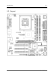
Introduction 1-3 1.2.
1-4 Chapter 1 1.3.
Hardware Setup Chapter 2. 2-1 Hardware Setup Before the Installation: Turn off the power supply switch (fully turn off the +5V standby power), or disconnect the power cord before installing or unplugging any connectors or add-on cards. Failing to do so may cause the motherboard components or add-on cards to malfunction or damaged. 2.1.
2-2 Chapter 2 2.2. Install Pentium® 4 CPU and Heatsink Supporting-Base This motherboard provides a ZIF (Zero Insertion Force) Socket 478 to install Intel® Pentium® 4 CPU. The CPU you bought should have a kit of heatsink and cooling fan along with. If that’s not the case, buy one specially designed for Pentium® 4 Socket 478. 1. Locate the 478-pin ZIF socket on the motherboard. Fasten the Retention Module Base onto the motherboard.
Hardware Setup 2-3 5. Push down the Retention Lock at both sides of the Fan and Retention Mechanism Assembly to lock up together with the Retention Module Base. 6. The Fan and Retention Mechanism Assembly and Retention Module Base should now firmly lock up with each other with the heatsink inside. ATTENTION: Do not forget to set the correct bus frequency and multiple for your processor. 2.3.
2-4 2.3.2. Chapter 2 Installing and Removing Memory Modules Power off the computer and unplug the AC power cord before installing or removing memory modules. 1. Locate the DIMM slot on the board. 2. Hold two edges of the DIMM module carefully, keep away of touching its connectors. 3. Align the two notch keys on the module with the two ribs on the slot. 4. Firmly press the module into the slots until the ejector tabs at both sides of the slot automatically snaps into the mounting notch.
Hardware Setup 2-5 2.4. Connectors, Headers, and Switches All the connectors, headers and switches mentioned here are depending on your system configuration. Some features you may (or may not) have to connect or to configure depending on the peripherals you have connected. WARNING: Always power off the computer and unplug the AC power cord before adding or removing any peripheral or component. Failing to so may cause severe damage to your system board and/or peripherals.
2-6 2.4.2. Chapter 2 FAN Power Connectors These 3-pin connectors each provide power to the cooling fans installed in your system. The CPU must be kept cool by using a powerful fan with heatsink. The system is capable of monitoring the speed of the CPU fan. • CPUFAN1: CPU Fan Power Connector • SYSFAN1: System Fan Power Connector • AUXFAN1: Auxiliary Fan Power Connector WARNING: These fan connectors are not jumpers. DO NOT place jumper caps on these connectors.
Hardware Setup 2.4.3. 2-7 CMOS Memory Clearing Header This header uses a jumper cap to clear the CMOS memory. • Pin 1-2 shorted (default): Normal operation. • Pin 2-3 shorted: Clear CMOS memory. ATTENTION: Turn the system power off first (including the +5V standby power) before clearing the CMOS memory. Failing to do so may cause your system to work abnormally or malfunction.
2-8 2.4.4. Chapter 2 AGP Display Card Slot (IS-10/IS-11/IS-12) This slot supports an optional AGP graphics card up to AGP 4X/8X mode. ATTENTION: This motherboard does not support 3.3V AGP cards. Use only 1.5V or 0.8V AGP cards.
Hardware Setup 2.4.5. 2-9 Front Panel Switches & Indicators Connection Headers These headers are used for connecting switches and LED indicators on the chassis front panel. The mark “+” align to the pin in the figure below stands for positive polarity for the LED connection. • HLED (Pin 1, 3): Connects to the HDD LED cable of chassis front panel. • RST (Pin 5, 7): Connects to the Reset Switch cable of chassis front panel. • SPK (Pin 15, 17, 19, 21): Connects to the System Speaker cable of chassis.
2-10 2.4.6. Chapter 2 Front Panel Audio Connection Header This header provides the connection to audio connector located at front panel. • To use the audio connector at front panel, remove all the jumpers on this header, and then connect to front panel by the extension cable provided with the chassis. • To use the audio connector at rear panel, disconnect the extension cable, attach the jumpers back at pin 5-6, and pin 9-10 (default setting).
Hardware Setup 2.4.7. 2-11 Additional USB Port Connection Headers These headers each provide two additional USB port connections.
2-12 2.4.8. Chapter 2 System Management Bus Connection Header This header provides one additional System Management Bus connection.
Hardware Setup 2.4.9. 2-13 Additional IEEE1394 Port Connection Headers (IS-12) These headers each provide one additional IEEE1394 port connection.
2-14 2.4.10. Chapter 2 Internal Audio Source Connectors These connectors provide the connection to the audio output of internal CD-ROM drive or add-on audio card.
Hardware Setup 2.4.11. 2-15 Floppy and IDE Disk Drive Connectors The FDC1 connector connects up to two floppy drives with a 34-wire, 2-connector floppy cable. Connect the single end at the longer length of ribbon cable to the FDC1 on the board, the two connectors on the other end to the floppy disk drives connector. Generally you need only one floppy disk drive in your system. NOTE: The red line on the ribbon cable must be aligned with pin-1 on both the FDC1 port and the floppy connector.
2-16 2.4.12. Chapter 2 Serial ATA Connectors These connectors each provide one Serial ATA channel connection.
Hardware Setup 2.4.13. 2-17 CPU Core Voltage Selector This header uses a jumper to adjust the CPU core voltage. • Pin 1-2 shorted (default): Normal operation. • Pin 2-3 shorted: Raise the CPU core voltage by 0.1V.
2-18 2.4.14. Chapter 2 External I/O Panel Connectors • Mouse: Connects to PS/2 mouse. • Keyboard: Connects to PS/2 keyboard. • LPT1: Connects to printer or other devices that support this communication protocol. • COM1: Connects to external modem, mouse or other devices that support this communication protocol. • VGA1: Connects to monitor input. • AUDIO1: R.L./R.R. (Rear Left / Rear Right): Connects to the rear left and rear right channel in the 5.1 channel audio system. Cen./Sub.
BIOS Setup Chapter 3. 3-1 BIOS Setup This motherboard provides a programmable EEPROM that you can update the BIOS utility. The BIOS (Basic Input/Output System) is a program that deals with the basic level of communication between processor and peripherals. Use the BIOS Setup program only when installing motherboard, reconfiguring system, or prompted to “Run Setup”. This chapter explains the Setup Utility of BIOS utility.
3-2 Chapter 3 3.1. Standard CMOS Features Date (mm:dd:yy) This item sets the date you specify (usually the current date) in the format of [Month], [Date], and [Year]. Time (hh:mm:ss) This item sets the time you specify (usually the current time) in the format of [Hour], [Minute], and [Second].
BIOS Setup 3-3 IDE Channel 1 Master/Slave, IDE Channel 2 Master/Slave Click key to enter its submenu: IDE HDD Auto-Detection This item allows you to detect the parameters of IDE drives by pressing the key. The parameters will automatically be shown on the screen. IDE Primary Master When set to [Auto], the BIOS will automatically check what kind of IDE drive you are using.
3-4 Chapter 3 Cylinder This item configures the numbers of cylinders. Head This item configures the numbers of read/write heads. Precomp This item displays the number of cylinders at which to change the write timing. Landing Zone This item displays the number of cylinders specified as the landing zone for the read/write heads. Sector This item configures the numbers of sectors per track. Drive A This item sets the type of floppy drives installed.
BIOS Setup 3-5 [All Errors]: The system-boot will stop whenever the BIOS detect a non-fatal error. [No Errors]: The system-boot will not stop for any error detected. [All, But Keyboard]: The system-boot will stop for all errors but keyboard error. [All, But Diskette]: The system-boot will stop for all errors but disk error. [All, But Disk/Key]: The system boot will stop for all errors but disk or keyboard error. Base Memory This item displays the amount of base memory installed in the system.
3-6 Chapter 3 3.2. Advanced BIOS Features Hyper-Threading Technology This item is used to enable the functionality of the processor with Hyper-Threading Technology and will appear only when using such processor. The Hyper-Threading Technology helps your PC work more efficiently by maximizing processor resources and enabling a single processor to run two separate threads of software simultaneously, bringing forth greater performance and system responsiveness when running multiple applications at once.
BIOS Setup 3-7 CPU L3 Cache This item is used to enable the L3 cache (default setting), and appears only for certain CPU (Intel Pentium 4 processor with HT Technology Extreme Edition) that possesses L3 cache. First Boot Device / Second Boot Device / Third Boot Device / Boot Other Device This item selects the drive to boot first, second and third in the [First Boot Device], [Second Boot Device], and [Third Boot Device] fields respectively.
3-8 Chapter 3 3.3. Advanced Chipset Features DRAM Timing Selectable This item sets the optimal timings for the following four items, depending on the memory module you are using. The default setting “By SPD” configures these four items by reading the contents in the SPD (Serial Presence Detect) device. The EEPROM on the memory module stores critical parameter information about the module, such as memory type, size, speed, voltage interface, and module banks.
BIOS Setup 3-9 AGP Aperture Size This option specifies the amount of system memory that can be used by the AGP device. The aperture is a portion of the PCI memory address range dedicated for graphics memory address space. Init Display First This item selects to initialize Onboard/AGP or PCI Slot first when the system boots. On-Chip VGA This option enables or disables the on-chip VGA controller. Frame Buffer Size This option selects the size of on-chip frame buffer.
3-10 Chapter 3 3.4.
BIOS Setup 3-11 IDE Bus Master This option enables or disables the IDE bus mastering capability under the DOS environment. Onboard IDE-1 Controller This item enables or disables the onboard IDE-1 controller. Onboard IDE-2 Controller This item enables or disables the onboard IDE-2 controller. Onboard S-ATA Controller This item determines the function for on-chip Serial ATA. [Disabled]: Disable the Serial ATA controller. [Auto]: Allows the Serial ATA controller to be arranged by BIOS automatically.
3-12 Chapter 3 Serial ATA Port1 Mode / Serial ATA Port2 Mode This item determines the function mode for Serial ATA Port 1 (i.e. The SATA1 connector in this model) and Serial ATA Port 2 (i.e. The SATA2 connector in this model).
BIOS Setup 3-13 Onboard PCI Device: Click key to enter its submenu: USB Controller This option enables or disables the USB controller. USB 2.0 Controller This option enables or disables the USB 2.0 controller. USB Keyboard Support This item allows you to select [BIOS] for using USB keyboard in DOS environment, or [OS] in OS environment. USB Mouse Support This item allows you to select [BIOS] for using USB mouse in DOS environment, or [OS] in OS environment.
3-14 Chapter 3 Onboard LAN Boot ROM When set to [Enabled], this item allows the system to boot from network by the onboard LAN controller boot ROM. Onboard 1394 Controller (IS-12) This item enables or disables the onboard IEEE 1394 controller. SuperIO Device: Click key to enter its submenu: POWER ON Function This item selects the way you want your system to power on. [Password]: Use a password to power on the system, select this option then press . Enter your password.
BIOS Setup 3-15 [Keyboard 98]: Use the power-on button on the “Keyboard 98” compatible keyboard to power on the system. NOTE: The mouse wake up function can only be used with the PS/2 mouse, not with the COM port or USB type. Some PS/2 mice cannot wake up the system because of compatible problems. If the specs of your keyboard are too old, it may fail to power on. KB Power ON Password This item sets the password required in order to power on your computer.
3-16 Chapter 3 [3BC/IRQ7]: This option allows the parallel port to use [3BC/IRQ7] as its I/O port address. Parallel Port Mode This item specifies the parallel port mode. [SPP]: (Standard Parallel Port) Allows bi-directional parallel port operation at normal speed. [EPP]: (Enhanced Parallel Port) Allows bi-directional parallel port operation at maximum speed. [ECP]: (Extended Capabilities Port) Allows bi-directional parallel port operation at a speed faster than the normal mode’s data transfer rate.
BIOS Setup 3-17 3.5. Power Management Setup ACPI Suspend Type This item selects the type of Suspend mode. [S1(POS)]: Enables the Power On Suspend function. [S3(STR)]: Enables the Suspend to RAM function. USB Dev Wake-Up From S3 When set to [Enabled], this item allows you to use a USB device to wake up a system that is in the S3 (STR - Suspend To RAM) state. This item can only be configured if the [ACPI Suspend Type] field is set to [S3(STR)].
3-18 Chapter 3 Wake-Up by PCI card/LAN When set to [Enabled], access to the onboard LAN or a PCI card such as a modem or LAN card will cause the system to wake up. The PCI card must support the wake up function. Power On by Ring Two options are available: Enabled and Disabled. Default setting is Disabled. If you connect an external modem to the onboard serial port, the system will be turned on when a telephone ring-up occurs.
BIOS Setup 3-19 3.6. PnP/PCI Configurations Force Update ESCD If you want to clear ESCD data next time you boot up, and ask the BIOS to reset the settings for the Plug & Play ISA Card and the PCI Card, select Enabled. But the next time you boot up, this option will automatically be set as Disabled. NOTE: The ESCD (Extended System Configuration Data) contains the IRQ, DMA, I/O port, memory information of the system. This is a specification and a feature specific to the Plug & Play BIOS.
3-20 IRQ Resources Click key to enter its submenu: This item sets each system interrupt to either [PCI Device] or [Reserved].
BIOS Setup 3-21 3.7. PC Health Status Shutdown Temperature This item sets the temperature that would shutdown the system automatically in order to prevent system overheats. CPU Warning Temperature This item selects the CPU’s warning temperature limit. Once the system has detected that the CPU’s temperature exceeded the limit, warning beeps will sound. NOTE: The onboard hardware monitor function is capable of detecting these system health conditions.
3-22 Chapter 3 NOTE: The hardware monitoring features for temperatures, fans and voltages will occupy the I/O address from 294H to 297H. If you have a network adapter, sound card or other add-on cards that might use those I/O addresses, please adjust your add-on card I/O address to avoid using these addresses. 3.8. Load Fail-Safe Defaults This option loads the BIOS default values for the most stable, minimal-performance system operations. 3.9.
Driver Installation Chapter 4. 4-1 Driver Installation All the necessary drivers are included within the Drivers & Utilities CD that came packaged with your board. The display shown in the following figure should appear after inserting this CD into your CD-ROM drive, if not, enter [My Computer] [CD-ROM] Drive double click [autorun.exe]. Please follow the on-screen instruction.
4-2 Chapter 4 4.1. Setup Items • Intel Chipset Software Utility Install the Intel chipset driver for Windows Operating System. • Intel Extreme Graphics Driver Install Intel graphics adapter driver for Windows Operating System. • Audio Driver Install the audio driver for Windows Operating System. • LAN Driver Install the LAN driver for Windows Operating System. • USB 2.0 Driver Install the USB 2.0 driver for Windows Operating System. • Manual View the user’s manual in PDF file.
How to Get Technical Support A-1 Appendix A. How to Get Technical Support (From our website) http://www.abit.com.tw (In North America) http://www.abit-usa.com (In Europe) http://www.abit.nl Thank you for choosing ABIT products. ABIT sells all our products through distributors, resellers and system integrators; we have no direct sales to end-users.
A-2 Appendix A 4. Internet Newsgroups. They are a great source of information and many people there can offer help. ABIT's Internet News group, alt.comp.periphs.mainboard.abit, is an ideal forum for the public to exchange information and discuss experiences they have had with ABIT products. Many times you will see that your question has already been asked before. This is a public Internet news group and it is reserved for free discussions. Here is a list of some of the more popular ones: alt.comp.periphs.
How to Get Technical Support A-3 North America and South America: ABIT Computer (U.S.A.) Corporation 45531 Northport Loop West, Fremont, California 94538, U.S.A. Tel: 1-510-623-0500 Fax: 1-510-623-1092 sales@abit-usa.com technical@abit-usa.com http://www.abit-usa.com U.K. and Ireland: ABIT Computer (U.K.) Corporation Ltd. Unit 3, 24-26 Boulton Road, Stevenage, Herts SG1 4QX, U.K. Tel: 44-1438-228888 Fax: 44-1438-226333 sales@abitcomputer.co.uk technical@abitcomputer.co.
A-4 Appendix A Japan: ABIT Computer (Japan) Co. Ltd. Fax: 81-3-5396-5110 http://www.abit4u.jp Shanghai: ABIT Computer (Shanghai) Co. Ltd. Tel: 86-21-6235-1829 Fax: 86-21-6235-1832 http://www.abit.com.cn Russia: ABIT Computer (Russia) Co. Ltd. Fax: 7-095-937-2837 techrussia@abit.com.tw http://www.abit.ru France, Italy, Spain, Portugal, and Greece: ABIT Computer France SARL Tel: 33-1-5858-0043 Fax: 33-1-5858-0047 http://www.abit.
How to Get Technical Support A-5 7. RMA Service. If your system has been working but it just stopped, but you have not installed any new software or hardware recently, it is likely that you have a defective component. Please contact the reseller from whom you bought the product. You should be able to get RMA service there. 8. Reporting Compatibility Problems to ABIT.
A-6 Appendix A Technical Support Form Company Name: Phone Number: Contact Person: Fax Number: E-mail Address: Model * Motherboard Model No.