IS7 Series (IS7-G, IS7, IS7-E, IS7-E2, IS7-E2G, IS7-E2V, IS7-M, IS7-V2) Intel Pentium 4 System Board Socket 478 User’s Manual 4200-0375-11 Rev. 1.
Copyright and Warranty Notice The information in this document is subject to change without notice and does not represent a commitment on part of the vendor, who assumes no liability or responsibility for any errors that may appear in this manual. No warranty or representation, either expressed or implied, is made with respect to the quality, accuracy or fitness for any particular part of this document.
Table Of Contents Chapter 1. 1-1. 1-2. 1-3. 1-4. 1-5. Chapter 2. 2-1. 2-2. 2-3. 2-4. Hardware Setup.................................................................... 2-1 Install The Motherboard...........................................................................2-1 Install Pentium® 4 CPU and Heatsink Supporting-Base..........................2-2 Install System Memory ............................................................................2-3 Connectors, Headers and Switches ...................
3-7. 3-8. 3-9. 3-10. 3-11. 3-12. 3-13. PnP/PCI Configurations.........................................................................3-22 PC Health Status ....................................................................................3-24 Load Fail-Safe Defaults .........................................................................3-25 Load Optimized Defaults .......................................................................3-25 Set Password ...................................................
Introduction 1-1 Chapter 1. Introduction 1-1. Features & Specifications 1. CPU • • Supports Intel Pentium 4 Socket 478 processor with 800MHz, 533MHz, and 400MHz (for Northwood only) System Data Bus Supports Intel Hyper-Threading Technology 2.
1-2 Chapter 1 9. Audio • • Onboard 6-Channel AC 97 CODEC Professional digital audio interface supports S/PDIF In/Out (IS7-G/IS7/IS7-E) 10. ABIT Engineered • • • • ABIT SoftMenu™ Technology ABIT EQ™ (IS7-G/IS7/IS7-E/IS7-E2/IS7-M/IS7-V2) ABIT FANEQ™ (IS7-G/IS7/IS7-E/IS7-M/IS7-E2) ABIT FlashMenu™ 11. Internal I/O Connectors • • • • • • • • • • • • 1x AGP slot 5x PCI slots 1x Floppy port supports up to 2.
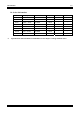
Introduction 1-3 14. Order Information Model IS7-G IS7 IS7-E IS7-E2 IS7-E2G IS7-E2V IS7-M IS7-V2 Chipset 865PE + ICH5R 865PE + ICH5R 865PE + ICH5 865PE + ICH5 865PE + ICH5 865PE + ICH5 865G + ICH5 848P + ICH5 LAN 10/100/1000M 10/100M 10/100M 10/100M 10/100/1000M 10/100M 10/100M SB SATA RAID 0/1 RAID 0/1 2 Ports 2 Ports 2 Ports 2 Ports 2 Ports 2 Ports PCI SATA RAID 0/1 - IEEE 1394 3 Ports 3 Ports - Specifications and information contained herein are subject to change without notice.
1-4 1-2.
Introduction 1-5 1-3.
1-6 1-4.
Introduction 1-7 1-5.
1-8 IS7 Series Chapter 1
Hardware Setup 2-1 Chapter 2. Hardware Setup Before the Installation: Turn off the power supply switch (fully turn off the +5V standby power), or disconnect the power cord before installing or unplugging any connectors or add-on cards. Failing to do so may cause the motherboard components or add-on cards to malfunction or damaged. 2-1.
2-2 Chapter 2 2-2. Install Pentium® 4 CPU and Heatsink Supporting-Base This motherboard provides a ZIF (Zero Insertion Force) Socket 478 to install Intel® Pentium® 4 CPU. The CPU you bought should have a kit of heatsink and cooling fan along with. If that’s not the case, buy one specially designed for Pentium® 4 Socket 478. 1. Locate the 478-pin ZIF socket on the motherboard. Fasten the Retention Module Base onto the motherboard.
Hardware Setup 2-3 2-3. Install System Memory IS7-G/IS7/IS7-E/IS7-M: This motherboard provides four 184-pin DDR DIMM slots for Single/Dual Channel DDR 400/333/266 memory modules with memory expansion size up to 4GB. To reach the performance of Dual Channel DDR, the following rules must be obeyed: • When installing TWO DIMM modules: Install DIMM modules of the same type and size for slots [DIMM1]+[DIMM3] or slots [DIMM2]+[DIMM4].
2-4 Chapter 2 IS7-E2/IS7-E2G/IS7-E2V/IS7-V2: This motherboard provides 2 184-pin DDR DIMM sites for memory expansion available from minimum 128MB to maximum 2GB. IS7-E2/IS7-E2G/IS7-E2V: IS7-V2: Bank Memory Module Total Memory Bank 0, 1 (DIMM1) 128, 256, 512MB, 1GB 128MB ~ 1GB Bank 2, 3 (DIMM2) 128, 256, 512MB, 1GB 128MB ~ 1GB Total System Memory 128MB ~ 2GB NOTE: No hardware or BIOS setup required after adding or removing memory modules.
Hardware Setup 2-5 Power off the computer and unplug the AC power cord before installing or removing memory modules. 1. Locate the DIMM slot on the board. 2. Hold two edges of the DIMM module carefully, keep away of touching its connectors. 3. Align the notch key on the module with the rib on the slot. 4. Firmly press the module into the slots until the ejector tabs at both sides of the slot automatically snaps into the mounting notch.
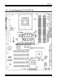
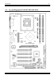
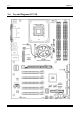
2-6 Chapter 2 2-4. Connectors, Headers and Switches Here we will show you all of the connectors, headers and switches, and how to connect them. Please read the entire section for necessary information before attempting to finish all the hardware installation inside the computer chassis. A complete enlarged layout diagram is shown in Chapter 1 for all the position of connectors and headers on the board that you may refer to.
Hardware Setup (2). 2-7 FAN Power Connectors These 3-pin connectors each provide power to the cooling fans installed in your system. The CPU must be kept cool by using a powerful fan with heatsink. The system is capable of monitoring the speed of the CPU fan. • CPUFAN1: CPU Fan Power Connector • NBFAN1: Chipset Fan Power Connector • SYSFAN1: System Fan Power Connector • AUXFAN1, AUXFAN2: Auxiliary Fan Power Connector WARNING: These fan connectors are not jumpers.
2-8 (3). Chapter 2 CMOS Memory Clearing Header This header uses a jumper cap to clear the CMOS memory. • Pin 1-2 shorted (default): Normal operation. • Pin 2-3 shorted: Clear CMOS memory. IS7-G/IS7/IS7-E: IS7-M: IS7-E2/IS7-E2G/IS7-E2V: IS7-V2 WARNING: Turn the power off first (including the +5V standby power) before clearing the CMOS memory. Failing to do so may cause your system to work abnormally or malfunction.
Hardware Setup (4). 2-9 Wake-up Header These headers use a jumper cap to enable/disable the wake-up function. • PS2-PWR1: Pin 1-2 shorted (default): Disable wake-up function support at Keyboard/Mouse port. Pin 2-3 shorted: Enable wake-up function support at Keyboard/Mouse port • USB-PWR1: Pin 1-2 shorted (default): Disable wake-up function support at USB1 port. Pin 2-3 shorted: Enable wake-up function support at USB1 port.
2-10 (5). Chapter 2 Front Panel Audio Connection Header This header provides the connection to audio connector at front panel. • To use the audio connector at front panel, remove all the jumpers on this header, and then connect to front panel by the extension cable provided with the chassis. • To use the audio connector at rear panel, disconnect the extension cable, attach the jumpers back at pin 5-6, and pin 9-10 (default setting).
Hardware Setup 2-11 IS7-E2/IS7-E2G/IS7-E2V: IS7-V2 Pin 1 3 5 7 9 Pin Assignment Audio Mic. Audio Mic.
2-12 (6). Chapter 2 Front Panel Switches & Indicators Headers This header is used for connecting switches and LED indicators on the chassis front panel. Watch the power LED pin position and orientation. The mark “+” align to the pin in the figure below stands for positive polarity for the LED connection. Please pay attention to connect these headers. A wrong orientation will only cause the LED not lighting, but a wrong connection of the switches could cause system malfunction.
Hardware Setup • HLED (Pin 1, 3): Connects to the HDD LED cable of chassis front panel. • RST (Pin 5, 7): Connects to the Reset Switch cable of chassis front panel. • SPK (Pin 15, 17, 19, 21): Connects to the System Speaker cable of chassis. • SLED (Pin 2, 4): Connects to the Suspend LED cable (if there is one) of chassis front panel. • PWR-ON (Pin 6, 8): Connects to the Power Switch cable of chassis front panel. • PLED (Pin 16, 18, 20): Connects to the Power LED cable of chassis front panel.
2-14 Chapter 2 (7). Infrared Device Header This header connects to an optional IR device attached to chassis. This motherboard supports standard IR transfer rates.
Hardware Setup 2-15 (8). Additional IEEE1394 Port Headers These headers each provide one additional IEEE1394 port connection through an extension cable and bracket.
2-16 (9). Chapter 2 Additional USB Port Headers These headers each provide 2 additional USB 2.0 ports connection through an USB cable designed for USB 2.0 specifications.
Hardware Setup 2-17 (10). System Management Bus Headers This header is reserved for system management bus (SM bus). The SM bus is a specific implementation of an I2C bus. I2C is a multi-master bus, which means that multiple chips can be connected to the same bus and each one can act as a master by initiating a data transfer. If more than one master simultaneously tries to control the bus, an arbitration procedure decides which master gets priority.
2-18 (11). Internal Audio Connectors These connectors connect to the audio output of internal CD-ROM drive or add-on card.
Hardware Setup IS7-E2/IS7-E2G/IS7-E2V: 2-19 IS7-V2: User’s Manual
2-20 Chapter 2 (12). Accelerated Graphics Port Slot This slot supports an optional AGP graphics card up to AGP 4X/8X mode. ATTENTION: This motherboard does not support 3.3V AGP cards. Use only 1.5V or 0.8V AGP cards.
Hardware Setup 2-21 (13). Floppy Disk Drive Connector This connector supports two standard floppy disk drives via a 34-pin 34-conductor ribbon cable. Connecting the Floppy Disk Drive Cable: 1. Install one end of the ribbon cable into the FDC1 connector. The colored edge of the ribbon cable should be aligned with pin-1 of FDC1 connector. 2. Install the other end(s) of ribbon cable into the disk drive connector(s).
2-22 Chapter 2 (14). IDE Connectors IS7-G/IS7/IS7-E: IS7-M: IS7-E2/IS7-E2G/IS7-E2V: IS7-V2: This motherboard provides two IDE ports to connect up to four IDE drives at Ultra ATA/100 mode by Ultra ATA/66 ribbon cables. Each cable has 40-pin 80-conductor and three connectors, providing two hard drives connection with motherboard.
Hardware Setup 2-23 (15). Serial ATA Connectors These connectors are provided to attach one Serial ATA device at each channel via Serial ATA cable.
2-24 Chapter 2 IS7-E2/IS7-E2G/IS7-E2V: IS7-V2: SATA1 and SATA2 are controlled by South Bridge. To enable the SATA1 and SATA2 controller, you have to enable the item “OnChip Serial ATA” first in the BIOS menu of “OnChip IDE Device”. The following table displays the quantity of devices at IDE1, IDE2, SATA1 and SATA2 channel under different “OnChip Serial ATA” configuration: WinXP / Windows .
Hardware Setup 2-25 (16). Status Indicator • 5VSB: This LED lights up when the power supply is connected with power source. • VCC: This LED lights up when the system power is on.
2-26 IS7-E2/IS7-E2G/IS7-E2V: IS7 Series Chapter 2 IS7-V2:
Hardware Setup (17).
2-28 Chapter 2 • Mouse: Connects to PS/2 mouse. • Keyboard: Connects to PS/2 keyboard. • LPT1: Connects to printer or other devices that support this communication protocol. • COM1: Connects to external modem, mouse or other devices that support this communication protocol. • OPT1: This connector provides an S/PDIF-In connection through optical fiber to digital multimedia devices.
BIOS Setup 3-1 Chapter 3. BIOS Setup This motherboard provides a programmable EEPROM that you can update the BIOS utility. The BIOS (Basic Input/Output System) is a program that deals with the basic level of communication between processor and peripherals. Use the BIOS Setup program only when installing motherboard, reconfiguring system, or prompted to “Run Setup”. This chapter explains the Setup Utility of BIOS utility.
3-2 Chapter 3 3-1. SoftMenu Setup The SoftMenu utility is ABIT’s exclusive and ultimate solution in programming the CPU operating speed. All the parameters regarding CPU FSB speed, multiplier factor, the AGP & PCI clock, and even the CPU core voltage are all available at your fingertips. Brand Name: This item displays the CPU model name, for example: Intel Pentium (R) 4. Frequency: This item displays the processor speed. Cache Size: This item displays the L2 cache size of your CPU.
BIOS Setup 3-3 Multiplier Factor: This item selects the multiplier factors for your CPU if it is not locked. Estimated new CPU clock: This item displays the frequency sum up from the previous item [Ext. Clock] and [Multiplier Factor]. N/B Strap CPU As: This item sets the external hardware reset strap assigned to MCH (Memory Controller Hub). The options are: [PSB400], [PSB533], [PSB800], and [By CPU]. The default setting is By CPU.
3-4 Chapter 3 3-2. Standard CMOS Features This section contains the basic configuration parameters of the BIOS. These parameters include date, hour, VGA card, FDD, and HDD settings. Date (mm:dd:yy): This item sets the date you specify (usually the current date) in the format of [Month], [Date], and [Year]. Time (hh:mm:ss): This item sets the time you specify (usually the current time) in the format of [Hour], [Minute], and [Second].
BIOS Setup 3-5 IDE HDD Auto-Detection: This item allows you to detect the parameters of IDE drives by pressing key. The parameters will be shown on the screen automatically. IDE Channel 1 Master/Slave, IDE Channel 2 Master/Slave, Extended IDE Drive: When set to [Auto], the BIOS will automatically check what kind of IDE drive you are using. If you want to define your own drive by yourself, set it to [Manual] and make sure you fully understand the meaning of the parameters.
3-6 Chapter 3 [EGA/VGA]: (Enhanced Graphics Adapter/Video Graphics Array) For EGA, VGA, SVGA and PGA monitor adapters. [CGA 40]: (Color Graphics Adapter) Power up in 40-column mode. [CGA 80]: (Color Graphics Adapter) Power up in 80-column mode. [Mono]: (Monochrome adapter) Includes high-resolution monochrome adapters. Halt On: This item determines whether the system stops if an error is detected during system boot-up. [All Errors]: The system-boot will stop whenever the BIOS detect a non-fatal error.
BIOS Setup 3-7 3-3. Advanced BIOS Features Hyper-Threading Technology This item is used to enable the functionality of the processor with Hyper-Threading Technology and will appear only when using such processor. The Hyper-Threading Technology helps your PC work more efficiently by maximizing processor resources and enabling a single processor to run two separate threads of software simultaneously, bringing forth greater performance and system responsiveness when running multiple applications at once.
3-8 Chapter 3 First Boot Device / Second Boot Device / Third Boot Device / Boot Other Device: Select the drive to boot first, second and third in the [First Boot Device], [Second Boot Device], and [Third Boot Device] items respectively. The BIOS will boot the operating system according to the sequence of the drive selected. Set [Boot Other Device] to [Enabled] if you wish to boot from another device other than these three items.
BIOS Setup 3-9 Report No FDD For OS: When set to [Yes], this item allows you to run some older operating system without floppy disk drive. Leave this item to its default setting. Delay IDE Initial (Secs): This item allows the BIOS to support some old or special IDE devices by prolonging this delay time. A larger value will give more delay time to the device for which to initialize and to prepare for activation.
3-10 Chapter 3 3-4. Advanced Chipset Features DRAM Timing Selectable: This item sets the optimal timings for the following four items, depending on the memory module you are using. The default setting “By SPD” configures these four items by reading the contents in the SPD (Serial Presence Detect) device. The EEPROM on the memory module stores critical parameter information about the module, such as memory type, size, speed, voltage interface, and module banks.
BIOS Setup 3-11 Memory Hole At 15M-16M: When set to [Enabled], the memory address space at 15M-16M will be reserved for ISA expansion cards that specifically requires this setting. This makes the memory from 15MB and up unavailable to the system. Leave this item to its default setting. Delay Prior to Thermal: This item selects the delay time before thermal activation. AGP Aperture Size: This option specifies the amount of system memory that can be used by the AGP device.
3-12 Chapter 3 3-5. Integrated Peripherals OnChip IDE Device: Click key to enter its submenu: IDE Bus Master: This option enables or disables the IDE bus mastering capability under the DOS environment. OnChip IDE-1 Controller: This item allows you to enable or disable the primary and secondary IDE controller. Select [Disabled] if you want to add a different hard drive controller.
BIOS Setup 3-13 Master/Slave Drive Ultra DMA (For IS7-G, IS7, IS7-E, and IS7-M only) This item allows you to set the Ultra DMA in use. [Auto]: The BIOS will select the best available option after checking your hard drive or CD-ROM. [Disabled]: The BIOS will not detect these categories. If problem arises in using Ultra DMA devices, try disabling this item. OnChip IDE-2 Controller: The description is same as the OnChip IDE-1 Controller.
3-14 Chapter 3 Serial ATA 1 Mode / Serial ATA 2 Mode: This item determines the function mode for Serial ATA Port 1 (i.e. The SATA1 connector in this model) and Serial ATA Port 2 (i.e. The SATA2 connector in this model).
BIOS Setup 3-15 OnChip PCI Device: Click key to enter its submenu: OnChip USB Controller: This option enables or disables the USB controller. USB 2.0 Controller: This option enables or disables the USB 2.0 controller. USB Keyboard Support Via: This item allows you to select [BIOS] for using USB keyboard in DOS environment, or [OS] in OS environment. USB Mouse Support Via: This item allows you to select [BIOS] for using USB mouse in DOS environment, or [OS] in OS environment.
3-16 Chapter 3 SuperIO Device: Click key to enter its submenu: Onboard FDC Controller: This option enables or disables the onboard FDC controller. Onboard Serial Port: This item determines which I/O addresses the onboard Serial Port controller will access. [Auto]: The system automatically select an I/O address for the onboard Serial Port. [3F8/IRQ4, 2F8/IRQ3, 3E8/IRQ4, 2E8/IRQ3]: Allows you to manually select an I/O address for the onboard Serial Port.
BIOS Setup 3-17 UR2 Duplex Mode: This item selects the duplex mode required by the IR device connected to the IR port. Full-duplex mode permits simultaneous two-direction transmission. Half-duplex mode permits transmission in one direction only at a time. Refer to your IR KIT user's guide to find out which setting is correct. Onboard Parallel Port: This item specifies the I/O address used by the parallel port. [Disabled]: This option prevents the parallel port from accessing any system resources.
3-18 Chapter 3 Onboard PCI Device: Click key to enter its submenu: IEEE 1394 Controller: (For IS7-G and IS7 only) This option enables or disables the IEEE 1394 controller. Serial ATA Controller: (For IS7-G only) This option enables or disables the Serial ATA controller of Silicon Image PCI Chip SATA RAID ROM: This item allows you to use the boot ROM of on-chip Serial ATA RAID to boot-up system.
BIOS Setup 3-19 3-6. Power Management Setup ACPI Suspend Type: This item selects the type of Suspend mode. [S1(PowerOn Suspend)]: Enables the Power On Suspend function. [S3(Suspend To RAM)]: Enables the Suspend to RAM function. Resume by USB From S3: When set to [Enabled], this item allows you to use a USB device to wake up a system that is in the S3 (STR - Suspend To RAM) state. This item can be configured only if the item “ACPI Suspend Type” is set to [S3(STR)].
3-20 Chapter 3 WakeUp by Alarm: When set to [Enabled], you can set the date and time you would like the Soft-Off PC to power-on in the “Date (of Month) Alarm” and “Time (hh:mm:ss) Alarm” items. However, if the system is being accessed by incoming calls or the network (Resume On Ring/LAN) prior to the date and time set in these items, the system will give priority to the incoming calls or network instead.
BIOS Setup 3-21 Hot Key Power ON: This item powers on the system by pressing key plus one of each function key ( ~ ) simultaneously. Restore On AC Power Loss: This item selects the system action after an AC power failure. [Power Off]: When power returns after an AC power failure, the system’s power remains off. You must press the Power button to power-on the system. [Power On]: When power returns after an AC power failure, the system’s power will be powered on automatically.
3-22 Chapter 3 3-7. PnP/PCI Configurations Resources Controlled By: This item configures all of the boot and Plug-and-Play compatible devices. [Auto]: The system will automatically detect the settings. [Manual]: Choose the specific IRQ resources in the “IRQ Resources” menu. IRQ Resources: Click key to enter its submenu: This item sets each system interrupt to either [PCI Device] or [Reserved].
BIOS Setup 3-23 [Enabled]: Automatically assign an IRQ for the VGA card installed. [Disabled]: The IRQ that was previously occupied by the VGA card will be available for new device. Allocate IRQ To USB: (For IS7-G, IS7, IS7-E, and IS7-M only) This item assigns an IRQ for the USB device connected. [Enabled]: Automatically assign an IRQ for the USB device connected. [Disabled]: The IRQ that was previously occupied by the USB device connected will be available for new device.
3-24 Chapter 3 3-8. PC Health Status FAN Fail Alarm Selectable: This item selects the fan that will be monitored for malfunction. Shutdown When CPUFAN Fail: When set to [Enabled], the system will be shut down if the CPU fan is not running. CPU FanEQ Speed Control: (For IS7-G/IS7/IS7-E/IS7-E2/IS7-E2G/IS7-E2V only) This item allows you to control the CPU fan speed down to a specific percentage.
BIOS Setup 3-25 All Voltages, Fans Speed and Thermal Monitoring: These unchangeable items list the current status of the CPU and environment temperatures, fan speeds, and system power voltage. NOTE: The hardware monitoring features for temperatures, fans and voltages will occupy the I/O address from 294H to 297H. If you have a network adapter, sound card or other add-on cards that might use those I/O addresses, please adjust your add-on card I/O address to avoid using these addresses. 3-9.
3-26 IS7 Series Chapter 3
Install Intel Chipset Software Utility A-1 Appendix A. Install Intel Chipset Software Utility NOTE: Please install this Intel Chipset driver first after having installed the Windows operating system. The installation procedures and screen shots in this section are based on Windows XP operating system. For those of other OS, please follow its on-screen instruction. Insert the Driver & Utility CD into CD-ROM drive, it should execute the installation program automatically.
A-2 IS7 Series Appendix A
Install Intel Application Accelerator RAID (IS7-G, IS7) B-1 Appendix B. Install Intel Application Accelerator RAID (IS7-G, IS7) The installation procedures and screen shots in this section are based on Windows XP operating system. For those of other OS, please follow its on-screen instruction. Insert the Driver & Utility CD into CD-ROM drive, it should execute the installation program automatically. If not, double-click the execution file at the main directory of this CD to enter the installation menu.
B-2 Appendix B 5. Click [Next]. 6. Click [Finish] to complete setup.
BIOS Update Guide Intel Serial ATA RAID Configuration Utility (IS7-G, IS7) B-3 Create RAID Volume This item allows you to create a RAID array. The on-chip Serial ATA RAID supports the Stripe (RAID 0) and Mirror (RAID 1) RAID set. For the striped RAID set, the identical drives can read and write data in parallel to increase performance. The Mirrored RAID set creates a complete backup of your files. Striped and Mirrored RAID set requires 2 hard disks to do so. Main Menu Reboot your system.
B-4 Appendix B Delete RAID Volume Reset Disks to Non-RAID This item allows you to remove a RAID Array. This item allows you to reset all RAID data. Type if you want to reset all RAID data. • Press <↑↓> (up, down arrow) to select the RAID array you want to delete. • Press to delete the volume. • Press to return to previous menu. NOTE: After you have made and confirmed this selection, all the data stored in the hard disk will be lost.
Install Audio Driver C-1 Appendix C. Install Audio Driver The installation procedures and screen shots in this section are based on Windows XP operating system. For those of other OS, please follow its on-screen instruction. Insert the Driver & Utility CD into CD-ROM drive, it should execute the installation program automatically. If not, double-click the execution file at the main directory of this CD to enter the installation menu. After entering the installation menu, move your curser to [Drivers] tab.
C-2 IS7 Series Appendix C
Install LAN Driver D-1 Appendix D. Install LAN Driver In spite of the various LAN chips that may be utilized on i865 (i848) series motherboard, the Driver & Utility CD came packed with this motherboard detects the one you have automatically. To install the LAN driver, please insert the Driver & Utility CD into CD-ROM drive. It should execute the installation program automatically. If not, double-click the execution file at the main directory of this CD to enter the installation menu.
D-2 IS7 Series Appendix D
Install Silicon Serial ATA RAID Driver (IS7-G) E-1 Appendix E. Install Silicon Serial ATA RAID Driver (IS7-G) The installation procedures and screen shots in this section are based on Windows XP operating system. For those of other OS, please follow its on-screen instruction. Insert the Driver & Utility CD into CD-ROM drive, it should execute the installation program automatically. If not, double-click the execution file at the main directory of this CD to enter the installation menu.
E-2 6. Appendix E Click [Finish]. 7. Choose [Yes, I want to restart my computer now.], and click [Finish] to complete setup. 8. Check [Device Manager]. [Silicon Image SiI 3112 SATARaid Controller] is successfully installed. IS7 Series 9. To run the [SATARaid] application, click [Start] [All Programs] [SATARaid]. 10. This is the SATALink configuration menu. For more information on how to operate, please refer to the “Help” menu.
Install Silicon Serial ATA RAID Driver (IS7-G) BIOS Setup for Serial ATA RAID (IS7-G) The Silicon Serial ATA controller supports the RAID array of both Striped (RAID 0) and Mirrored (RAID 1). For the striped RAID set, the identical drives can read and write data in parallel to increase performance. The Mirrored RAID set creates a complete backup of your files. Striped and Mirrored RAID set requires 2 hard disks to do so.
E-4 Appendix E Option 2 Delete RAID set This item allows you to remove a RAID Array on this onboard Serial ATA RAID controller. NOTE: After you have made and confirmed this selection, all the data stored in the hard disk will be lost. (The entire partition configuration will be deleted too.) Option 3 Rebuild Mirrored set This item allows you to rebuild only “Mirrored” RAID set.
Install VGA Driver (IS7-M) F-1 Appendix F. Install VGA Driver (IS7-M) The installation procedures and screen shots in this section are based on Windows XP operating system. For those of other OS, please follow its on-screen instruction. Insert the Driver & Utility CD into CD-ROM drive, it should execute the installation program automatically. If not, double-click the execution file at the main directory of this CD to enter the installation menu.
F-2 IS7 Series Appendix F
Install USB 2.0 Driver G-1 Appendix G. Install USB 2.0 Driver NOTE: The “USB 2.0 Driver” packed in the “Driver & Utility CD” is currently available for Windows 9x and ME only. To install this driver for Windows XP or Windows 2000, you have to download their latest service pack first from Microsoft’s web site. To install the USB 2.0 driver for Windows 9x and ME, please insert the Driver & Utility CD into CD-ROM drive. It should execute the installation program automatically.
G-2 IS7 Series Appendix G
ABIT EQ (The Hardware Doctor Utility) H-1 Appendix H. ABIT EQ (The Hardware Doctor Utility) ABIT EQ is a self-diagnostic system for PC based on motherboards designed and manufactured by ABIT Computer Corporation. It will protect PC Hardware by monitoring critical items of Power Supply Voltage, CPU & System Fans Speed, and CPU & System Temperature. The installation procedures and screen shots in this section are based on Windows XP operating system.
H-2 5. Execute the ABIT EQ by entering the Windows Menu [Start] [Programs] [ABIT] [ABIT EQ]. 6. This screen appears. ABIT EQ shows you the status of Voltage, Fan Speed, and Temperature readings as well. (The item names in this screen shot are for reference only, may not be exactly the same as what you see on your monitor.
FlashMenu (BIOS Update Utility) Appendix I. I-1 FlashMenu (BIOS Update Utility) ABIT FlashMenu is the most stable Windows-based BIOS flash available. No more worries from crashing. With one click of BIOS updating, ABIT users can flash their BIOS more easily and in less time. The installation procedures and screen shots in this section are based on Windows XP operating system. For those of other OS, please follow its on-screen instruction.
I-2 6. This FlashMenu screen appears. You can easily update the BIOS from clicking [Update From File], [One Click LiveUpdate], or [LiveUpdate Step by Step] button.
Troubleshooting (Need Assistance?) J-1 Appendix J. Troubleshooting (Need Assistance?) Q & A: Q: Do I need to clear the CMOS before I use a new motherboard to assemble my new computer system? A: Yes, we highly recommend that you clear the CMOS before installing a new motherboard. Please move the CMOS jumper from its default 1-2 position to 2-3 for a few seconds, and then back. When you boot up your system for the first time, follow the instructions in the user's manual to load the optimized defaults.
J-2 Appendix J Q: How can I get a quick response to my request for technical support? A: Be sure to follow the guidelines as stated in the “Technical Support Form” section of this manual. If you have a problem during operation, in order to help our technical support personnel quickly determine the problem with your motherboard and give you the answers you need, before filling in the technical support form, eliminate any peripheral that is not related to the problem, and indicate it on the form.
Troubleshooting (Need Assistance?) J-3 Main instructions: To fill in this “Technical Support Form”, refer to the step-by-step instructions given below: 1*. MODEL: Note the model number given in your user’s manual. Example: IS7-G, IS7, IS7-E, IS7-E2, IS7-E2G, IS7-E2V, IS7-M, IS7-V2 * 2 . Motherboard model number (REV): Note the motherboard model number labeled on the motherboard as “REV:*.**”. Example: REV: 1.06 * 3 . BIOS ID and Part Number: See the on screen message. 4.
J-4 Appendix J Technical Support Form Company Name: Phone Number: Contact Person: Fax Number: E-mail Address: Model * Motherboard Model No.
Troubleshooting (Need Assistance?) K-1 Appendix K. How to Get Technical Support (From our website) http://www.abit.com.tw (In North America) http://www.abit-usa.com (In Europe) http://www.abit.nl Thank you for choosing ABIT products. ABIT sells all our products through distributors, resellers and system integrators; we have no direct sales to end-users.
K-2 Appendix K 4. Internet Newsgroups. They are a great source of information and many people there can offer help. ABIT's Internet News group, alt.comp.periphs.mainboard.abit, is an ideal forum for the public to exchange information and discuss experiences they have had with ABIT products. Many times you will see that your question has already been asked before. This is a public Internet news group and it is reserved for free discussions. Here is a list of some of the more popular ones: alt.comp.periphs.
Troubleshooting (Need Assistance?) North America, South America K-3 ABIT Computer (U.S.A.) Corporation 45531 Northport Loop West, Fremont CA, 94538, U.S.A. Tel: 1-510-623-0500 Fax: 1-510-623-1092 Sales: sales@abit-usa.com Latin America Sales: ventas@abit-usa.com Marketing: marketing@abit-usa.com Web Site: http://www.abit-usa.com RMA Center 46808 Lakeview Blvd. Fremont, CA 94538, U.S.A. UK and Ireland ABIT Computer (U.K.) Corporation Ltd.
K-4 Appendix K Poland Japan Taiwan Head Office (Serving all other territories not listed above. Taiwan is 8+ GMT time, and may have different holiday calendar from yours.) ABIT Computer (Poland) Co. Ltd. Przedstawicielstwo w Polsce ul. Wita Stwosza 28 50-149 Wrocław Tel: 48 71 780 78 65 / 66 Fax: 48 71 372 30 87 Web Site: http://www.abit4u.jp ABIT Computer Corporation No. 323, Yang Guang St., Neihu, Taipei, 114, Taiwan Tel: 886-2-8751-8888 Fax: 886-2-8751-3382 Sales: sales@abit.com.