SI7 Series (SI7, SI7-G) Socket 478 System Board User’s Manual 4200-0346-02 Rev. 1.
Copyright and Warranty Notice The information in this document is subject to change without notice and does not represent a commitment on part of the vendor, who assumes no liability or responsibility for any errors that may appear in this manual. No warranty or representation, either expressed or implied, is made with respect to the quality, accuracy or fitness for any particular part of this document.
Table Of Contents SI7 系列快速安裝指引 ............................................................................. 1 SI7 シリーズのクイックインストールガイド ..................................... 3 SI7-Serie Schnellinstallationsanleitung .................................................. 5 Série SI7 Guide d’Installation Rapide.................................................... 7 Краткое руководство по установке SI7 cерия ................................... 9 Guida all’installazione veloce Scheda madre serie SI7...................
Chapter 3. 3-1. 3-2. 3-3. 3-4. 3-5. 3-6. 3-7. 3-8. 3-9. 3-10. 3-11. 3-12. 3-13. BIOS Setup............................................................................ 3-1 SoftMenu Setup Features .........................................................................3-2 Standard CMOS Features.........................................................................3-4 Advanced BIOS Features.........................................................................3-6 Advanced Chipset Features...............
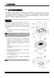
SI7 系列快速安裝指引 1 SI7 系列快速安裝指引 如您要瞭解此主機板更詳細的資訊,請參閱我們的完整版使用手冊,裡面會有詳盡的說明。此快速 安裝手冊是給有經驗的系統組裝者使用,如果這是您第一次嘗試來組裝您的電腦系統,我們建議您 先去閱讀完整版的使用手冊,或是詢問技術人員來幫助您組裝您的電腦系統(完整版的使用手冊已 包覆在隨本主機板所附的驅動程式與應用光碟之中)。 處理器的安裝 本主機板提供零出力 (Zero Insertion Force, ZIF) 式 Socket 478,以方便安裝 Intel® Pentium® 4 CPU。您所 購買的 CPU 應已配備一組散熱套件及散熱片,如果沒 有,請購買專為 Pentium® 4 Socket 478 設計的散熱套件 及散熱片。 1. 請找出 Socket 478 的位置,然後將散熱套件支座固 定在主機板上。 注意:若果您使用專為 Pentium® 4 設計的底座,請注意 底座上的金屬螺栓或墊片 (若已安裝的話)。請確定金屬 螺栓或墊片不會碰到印刷電路板上的電線或零件。 2.
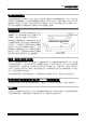
2 SI7 系列快速安裝指引 將主機板安裝到機殼上 當您將處理器安裝到主機板上之後,您便可以開始將主機板固定到電腦機殼裡去。首先;請您先將 主機板固定到電腦機殼。大多數的電腦機殼底座都有許多的固定孔位,請將主機板上的固定孔位與 機殼底座上的固定孔位對準。如果孔能對準並且有螺絲孔,就表示可使用銅柱來固定主機板。另外; 您可以使用塑膠墊片來讓螺絲與主機板的 PCB 表層隔離(絕緣)。 安裝系統記憶體 本主機板提供 2 組 232 腳的 RIMM 插座可供記 憶體擴充,可支援 RIMM 的最小記憶體大小為 128MB,而最大的記憶體大小則為 2GB。 將 RIMM 記憶體模組插入 RIMM 插槽。請注意 記憶體模組的楔子是如何對應到 RIMM 插槽上 的卡榫之上。此種設計可確保 RIMM 記憶體模 組僅能由一個方向插到 RIMM 插槽之上。當您 將 RIMM 記憶體模組完全插入 RIMM 插槽時, 模組退出(固定)夾應該會將 RIMM 記憶體模 組自兩側卡緊並緊緊地固定住記憶體模組。 連接器、連接頭以及附加卡的安裝 在任何一部電腦機殼的裡面,都必需連接一些纜線與插頭。這些纜線與插頭通常都是一對一的連接 至主機板
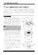
SI7 シリーズのクイックインストールガイド 3 SI7 シリーズのクイックインストールガイド このマザーボードの詳細については、ユーザーズマニュアルの完全版を参照してください。この クイックインストールガイドは、経験あるシステム構築者向けに書かれました。今回始めてコン ピュータシステムをセットアップする方は、まず完全版のマニュアルをお読みになるか、専門技 術者に連絡してコンピュータシステムのセットアップを行うようお勧めします(完全な利用者マ ニュアルはこのマザーボードによって詰められて来たドライバとユーティリティの CD の拾い 読みによって利用できる)。 プロセッサの取り付け このマザーボードは ZIF (ゼロインサーションフォー ス) Socket 478 を提供して Intel® Pentium® 4 CPU をイ ンストールします。お買い上げになった CPU には、 ヒートシンクと冷却ファンのキットが付属していま す。付属していない場合、Pentium® 4 Socket 478 向け に特別に設計されたキットをお求めください。 1.
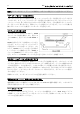
4 SI7 シリーズのクイックインストールガイド 注意:プロセッサに対して、正しいバス周波数とマルチプルに設定することを忘れないでください。 マザーボードをシャーシに取り付ける マザーボードにプロセッサを取り付けた後、シャーシにマザーボードを固定することができるよ うになります。まず、シャーシにマザーボードを固定する必要があります。ほとんどのコンピュ ータシャーシには、多くの取り付け穴の付いた台が付属しており、それを使用することでマザー ボードをしっかり取り付けたり、同時にショートを避けることができます。シャーシに付属する 飾りボタンかスペーサーを使用してマザーボードを固定します。 システムメモリの取り付け このマザーボードでは、2 つの 232 ピン RIMM スロットメモリ拡張を提供します。最小メモ リは 128MB で、最大メモリは 2GB RIMM で す。 RIMM を図に示すように拡張スロットに差し 込みます。モジュールがソケットにどのよう に固定されているか注意してください。これ により、RIMM モジュールに差し込む方法が 1 つしかないことを確認できます。RIMM モ ジュールを RIM
SI7-Serie Schnellinstallationsanleitung 5 SI7-Serie Schnellinstallationsanleitung Beziehen Sie sich bitte für detaillierte Informationen über diese Hauptplatine auf die vollständige Version des Benutzerbuchs. Diese Schnellinstallationsanleitung ist für erfahrene Systemaufbauer gedacht.
6 SI7-Serie Schnellinstallationsanleitung Achtung: Vergessen Sie nicht, die korrekte Busfrequenz und Multiplikator für Ihren Prozessor einzustellen. Installieren der Hauptplatine im Gehäuse Nach der Installation des Prozessors können Sie anfangen die Hauptplatine im Computergehäuse zu befestigen. Die meisten Gehäuse haben eine Bodenplatte, auf der sich eine Reihe von Befestigungslöcher befinden, mit deren Hilfe Sie die Hauptplatine sicher verankern können und zugleich Kurzschlüsse verhindern.
Série SI7 Guide d’Installation Rapide 7 Série SI7 Guide d’Installation Rapide Pour des informations relatives à cette carte mère plus détaillées, veuillez vous référer à notre version complète du manuel utilisateur. Ce guide d’installation rapide est créé pour les assembleurs système expérimentés.
8 Série SI7 Guide d’Installation Rapide 6. Le couvercle support et la base du dissipateur thermique doivent maintenant être fermement fixés l'un à l'autre fermement avec le dissipateur thermique à l'intérieur. Attention: N'oubliez pas de régler une fréquence de votre processeur. Bus et un coefficient multiplicateur corrects pour Installer la Carte Mre dans le Châssis Une fois que vous aurez installé le processeur sur la carte mère, vous pourrez commencer à fixer la carte mère sur le châssis.
Краткое руководство по установке SI7 cерия 9 Краткое руководство по установке SI7 cерия Более подробные сведения о материнской плате приведены в руководстве пользователя. Краткое руководство по установке предназначено для опытных специалистов. Если вы собираете компьютер впервые, ознакомьтесь сперва с руководством пользователя или попросите техника помочь в настройке компьютерной системы.
10 Краткое руководство по установке SI7 cерия Установка материнской платы в корпус После установки процессора на материнскую плату можно начинать установку материнской платы в корпус. Большая часть корпусов оборудована основанием, в котором проделаны монтажные отверстия, которые позволяют надежно закрепить материнскую плату и предотвратить короткие замыкания. Для крепления материнской платы к основанию используются винты и прокладки.
Guida all’installazione veloce Scheda madre serie SI7 11 Guida all’installazione veloce Scheda madre serie SI7 Per maggiori e dettagliate informazioni su questa scheda madre si prega di fare riferimento alla versione integrale del Manuale utente. Questa guida all’installazione veloce è intesa per costruttori esperi di sistemi.
12 Guida all’installazione veloce Scheda madre serie SI7 Attenzione: Non dimenticare di impostare la corretta frequenza BUS e multiplier per il processore. Installazione della scheda madre sul telaio Dopo avere installato il processore sulla scheda madre si può iniziare a fissare la scheda madre sul telaio. Innanzi tutto è necessario fissare la scheda madre al telaio.
Introduction 1-1 Chapter 1. Introduction 1-1. Features & Specifications 1. CPU • • Supports Intel® Pentium® 4 socket 478 processor with 400MHz/533MHz System Data Bus Supports Intel® Hyper-Threading Technology 2. Chipset • SiS R658 + SiS 963 • • Supports Hi-Speed Universal Serial Bus (USB 2.0) Supports Ultra ATA/133/100/66/33 mode 3. Memory • • Supports 2x 32-bit RIMM PC1200/PC1066/PC800 Direct RDRAM (2GB MAX) Supports configurable ECC function 4.
1-2 Chapter 1 • • • Supports Advanced Configuration Power Interface (ACPI) Supports Desktop Management Interface (DMI) AMI BIOS 12. Internal I/O Connectors • • • • • • • • 1x AGP slot 5x PCI slots 1x Floppy port supports up to 2.88MB 2x Ultra ATA/133/100/66/33 connectors 2x Serial ATA 150 connectors 2x USB headers 2x IEEE 1394 headers 1x CD-IN, 1x AUX-IN header 13.
Introduction 1-3 1-2.
1-4 SI7 Series Chapter 1
Hardware Setup 2-1 Chapter 2. Hardware Setup Before the Installation: Turn off the power supply switch (fully turn off the +5V standby power), or disconnect the power cord before installing or unplugging any connectors or add-on cards. Failing to do so may cause the motherboard components or add-on cards to malfunction or damaged. 2-1.
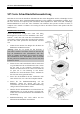
2-2 Chapter 2 2-2. Install Pentium® 4 CPU and Heatsink Supporting-Base This motherboard provides a ZIF (Zero Insertion Force) Socket 478 to install Intel® Pentium® 4 CPU. The CPU you bought should have a kit of heatsink and cooling fan along with. If that’s not the case, buy one specially designed for Pentium® 4 Socket 478. 1. Locate the Socket 478. Fasten the heatsink supporting-base onto the motherboard.
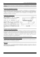
Hardware Setup 2-3 2-3. Install System Memory This motherboard provides two 232-pin 32-bit RIMM (Rambus Inline Memory Modules) slots for PC1200/PC1066/PC800 Direct RDRAM. ATTENTION: The PC1066 RIMM modules require CPU of 533MHz FSB only. Do not use PC1066 modules with CPU of 400MHz FSB. Table 2-1.
2-4 Chapter 2 The diagram below shows the possible combination of RDRAM installation. NOTE: No hardware or BIOS setup required after adding or removing memory modules. ATTENTION: Static electricity can damage the electronic components of the computer or optional boards. Before starting these procedures, ensure that you are discharged of static electricity by touching a grounded metal object briefly. Power off the computer and unplug the AC power cord before installing or removing memory modules. 1.
Hardware Setup 2-5 2-4. Connectors, Headers and Switches Here we will show you all of the connectors, headers and switches, and how to connect them. Please read the entire section for necessary information before attempting to finish all the hardware installation inside the computer chassis. A complete enlarged layout diagram is shown in Chapter 1 for all the position of connectors and headers on the board that you may refer to.
2-6 (2). Chapter 2 FAN Connectors [CPUFAN1, SYSFAN1, AUXFAN1] These 3-pin connectors each provide power to the cooling fans installed in your system. The CPU must be kept cool by using a powerful fan with heatsink. The system is capable of monitoring the speed of the CPU fan. • CPUFAN1: CPU Fan • SYSFAN1: System Fan • AUXFAN1: Auxiliary Fan WARNING: These fan connectors are not jumpers. DO NOT place jumper caps on these connectors.
Hardware Setup (3). 2-7 CMOS Memory Clearing Header [CCMOS1] This header uses a jumper cap to clear the CMOS memory. • Pin 1-2 shorted (default): Normal operation. • Pin 2-3 shorted: Clear CMOS memory. WARNING: Turn the power off first (including the +5V standby power) before clearing the CMOS memory. Failing to do so may cause your system to work abnormally or malfunction.
2-8 (4). Chapter 2 Front Panel Audio Connection Header [FP-AUDIO1] This header provides the connection to audio connector at front panel (with optional ABIT Media XP). • To use the audio connector at front panel, remove all the jumpers on this header, and then connect to front panel by the extension cable provided with the chassis. • To use the audio connector at rear panel, disconnect the extension cable, attach the jumpers back at pin 5-6, and pin 9-10 (default setting).
Hardware Setup (5). 2-9 Additional USB Port Headers [FP-USB1, FP-USB2] These headers each provide 2 additional USB 2.0 ports connection through an USB cable designed for USB 2.0 specifications.
2-10 Chapter 2 (6). Additional IEEE1394 Port Headers [FP-1394-1, FP-1394-2] These headers each provide 1 additional IEEE1394 port connection through an extension cable and bracket.
Hardware Setup (7). 2-11 Front Panel Switches & Indicators Headers [FPIO1] This header is used for connecting switches and LED indicators on the chassis front panel. Watch the power LED pin position and orientation. The mark “+” align to the pin in the figure below stands for positive polarity for the LED connection. Please pay attention to connect these headers. A wrong orientation will only cause the LED not lighting, but a wrong connection of the switches could cause system malfunction.
2-12 (8). Chapter 2 System Management Bus Header [SMB1] This header is reserved for system management bus (SM bus). The SM bus is a specific implementation of an I2C bus. I2C is a multi-master bus, which means that multiple chips can be connected to the same bus and each one can act as a master by initiating a data transfer. If more than one master simultaneously tries to control the bus, an arbitration procedure decides which master gets priority. (9).
Hardware Setup 2-13 (10). Accelerated Graphics Port Slot [AGP1] This slot supports an optional AGP graphics card up to AGP 4X/8X mode. Please refer to our Web site for more information on graphics cards. ATTENTION: This motherboard does not support 3.3V AGP cards. Use only 1.5V or 0.8V AGP cards.
2-14 Chapter 2 (11). Floppy Disk Drive Connector [FDC1] This connector supports two standard floppy disk drives via a 34-pin 34-conductor ribbon cable. Connecting the Floppy Disk Drive Cable: 1. Install one end of the ribbon cable into the FDC1 connector. The colored edge of the ribbon cable should be aligned with pin-1 of FDC1 connector. 2. Install the other end(s) of ribbon cable into the disk drive connector(s).
Hardware Setup 2-15 (12). IDE Connectors [IDE1, IDE2] This motherboard provides two IDE ports to connect up to four IDE drives at Ultra ATA/100 mode by Ultra ATA/66 ribbon cables. Each cable has 40-pin 80-conductor and three connectors, providing two hard drives connection with motherboard.
2-16 Chapter 2 (13). Serial ATA Connectors [SATA1, SATA2] These two connectors are provided to attach one serial ATA device at each channel through Serial ATA cable. It is also possible to connect legacy IDE hard disk through an optional SERILLEL Converter.
Hardware Setup 2-17 (14). POST Code Display [U32] This is an LED device to display the “POST” Code, the acronym of Power On Self Test. The computer will execute the POST action whenever you power on the computer. The POST process is controlled by the BIOS. It is used to detect the status of the computer’s main components and peripherals. Each POST Code corresponds to different checkpoints that are also defined by the BIOS in advance.
2-18 Chapter 2 0A 0E 10 12 14 16 18 1B 1D 1F 21 23 27 29 2D 33 3C 3E 40 43 47 49 SI7 Series 1. Disable PS/2 mouse interface (optional) 2. Auto detect ports for keyboard & mouse followed by a port & interface swap (optional) 3. Reset keyboard for Winbond 977 series Super I/O chips Test F000h segment shadow to see whether it is R/W-able or not.
Hardware Setup 4E 50 52 55 57 59 5B 5D 60 65 67 69 6B 6D 6F 73 75 77 7A 7F 82 83 84 85 93 2-19 1. 2. 3. 4.
2-20 Chapter 2 94 95 96 FF 1. Enable L2 cache 2. Program boot up speed 3. Chipset final initialization 4. Power management final initialization 5. Clear screen & display summary table 6. Program K6 write allocation 7. Program P6 class write combining 1. Program daylight saving 2. Update keyboard LED & typematic rate 1. Build MP table 2. Build & update ESCD 3. Set CMOS century to 20h or 19h 4. Load CMOS time into DOS timer tick 5. Build MSIRQ routing table Boot attempt (INT 19h) (15).
Hardware Setup 2-21 (16). Status Indicators [D17, D14, D15, D18] • D17 (FORWARD): This LED lights up when moving forward to next code layer of the POST Code Displayer. • D14 (BACK): This LED lights up moving backward to previous code layer of the POST Code Displayer. • D15 (VCC): This LED lights up when the system power is on. • D18 (5VSB): This LED lights up when the power supply is connected with power source.
2-22 Chapter 2 (17). Back Panel Connectors [KM1, LPT1, COM1, COM2, OPT-OUT1, AUDIO1, AUDIO2, LAN, USB1] • Mouse: Connects to PS/2 mouse. • Keyboard: Connects to PS/2 keyboard. • LPT1: Connects to printer or other devices that support this communication protocol. • COM1/COM2: Connects to external modem, mouse or other devices that support this communication protocol. • OPT-OUT1: This connector provides an S/PDIF Out connection through optical fiber to digital multimedia devices. • AUDIO1: R.L.
BIOS Setup 3-1 Chapter 3. BIOS Setup This motherboard provides a programmable EEPROM that you can update the BIOS utility. The BIOS (Basic Input/Output System) is a program that deals with the basic level of communication between processor and peripherals. Use the BIOS Setup program only when installing motherboard, reconfiguring system, or prompted to “Run Setup”. This chapter explains the Setup Utility of BIOS utility.
3-2 Chapter 3 3-1. SoftMenu Setup Features The SoftMenu utility is ABIT’s exclusive and ultimate solution in programming the CPU operating speed. All the parameters regarding CPU FSB speed, multiplier factor, the AGP & PCI clock, and even the CPU core voltage are all available at your fingertips. Processor Type: This item displays the CPU model name, for example: Intel Pentium (R) 4. Processor Speed: This item displays the processor speed. Cache Size: This item displays the L2 cache size of your CPU.
BIOS Setup 3-3 There will be no guaranty for the settings beyond specification, any damage of any component on this motherboard or peripherals result therein is not our responsibility. CPU Front Side Bus Frequency: This item selects the FSB frequency for your CPU. The FSB speed above the CPU’s standard bus speed is supported but not guaranteed due to its specifications limit. CPU Ratio Selection: This item selects the multiplier factors for your CPU if it is not locked.
3-4 Chapter 3 3-2. Standard CMOS Features System Date: This item sets the date you specify (usually the current date) in the format of [Month], [Date], and [Year]. System Time: This item sets the time you specify (usually the current time) in the format of [Hour], [Minute], and [Second]. Floppy Driver A / Floppy Driver B: This item sets the type of floppy drives (usually only Drive A) installed.
BIOS Setup 3-5 IDE Primary Master/Slave and IDE Secondary Master/Slave: Click key to enter its submenu: Type: This item selects the type of your hard disk drives (HDD). Leave this option to its default [AUTO] settings to set all HDD parameters automatically. NOTE: A newly purchased IDE HDD must be first formatted. Cylinders: This item configures the numbers of cylinders. Heads: This item configures the numbers of read/write heads.
3-6 Chapter 3 Block Mode: This option allows you to select [On] for a hard disk using block mode. The system BIOS will check the hard disk drive for the maximum block size the system can transfer. The block size will depend on the type of hard disk drive. Select [Off] to use standard mode. Fast Programmed I/O Modes: This option allows you to select the PIO mode. Select [Auto] will enhance the hard disk performance by optimizing the hard disk timing.
BIOS Setup 3-7 How to use the Quick Boot function? When you start to get in the boot sequence, press key one time, then you can see the “Select First Boot Device” menu show up. Choose the first boot device you want then press key to continue the boot sequence. Boot Device Priority: This item selects the booting priority. The BIOS will boot the operating system according to the sequence of the drive selected.
3-8 Chapter 3 System BIOS Cacheable: Enabling the System BIOS cache will allow accesses to the system BIOS ROM addressed at F0000H-FFFFFH, if the cache controller is enabled. The larger the range of the Cache RAM, the higher the efficiency of the system will be. Video BIOS Cacheable: Enabling the Video BIOS cache will allow access to the video BIOS addressed at C0000H to C7FFFH to be cached, if the cache controller is enabled.
BIOS Setup 3-9 RAMBUS TDSEL Turbo Mode: Leave this item to its default setting. RAMBUS RDSEL Turbo Mode: Leave this item to its default setting. Cas Access Delay(tCAC): Leave this item to its default setting. Graphic Win Size: This item specifies the amount of system memory that can be used by AGP card. AGP Fast Write: If your AGP card supports this “Fast Write” function, this option will increase your system performance by selecting [Enabled], but it may also decrease system compatibility.
3-10 Chapter 3 MPS Revision: This option specifies which version of MPS (Multi-Processor Specification) this motherboard will use. Select [1.1] when using an older operating system for dual processor executing. Auto Turn Off Pci Clock Pin: This item turns off the PCI clock that is not in use. Leave this option to its default settings. 3-5. Power Management Features ACPI Standby State: This item selects the type of Suspend mode. • [S1(POS)]: Enables the Power On Suspend function.
BIOS Setup • 3-11 [Suspend]: Suspending the system. Restore on AC/Power loss: This item sets the system power state when it recovers from AC power loss. • [Power Off]: The system turns off when power returns. • [Power On]: The system turns on when power returns. • [Last State]: The system returns to the previous power state. Wake Up Events: Click key to enter its submenu: Keyboard PowerOn Function: This item selects the wake-up method by keyboard.
3-12 Chapter 3 Wake Up by PS2 Mouse: When set to [Enabled], any event occurring at PS/2 mouse port will awaken the system that has been powered down. PS2 MOUSE Wakeup Mode Select: This item selects the mode to awaken the system by PS/2 mouse. • [Normal]: Any movement of the mouse will affect. • [Only Button]: Only by pushing the mouse buttons will affect. Wake Up by PME: When set to [Enabled], any event occurring at LAN port will awaken the system that has been powered down.
BIOS Setup 3-13 3-6. PnP/PCI Configurations Plug and Play Aware O/S: This item allows you to use a PnP operating system to configure the PCI bus slots instead of the BIOS. When set to [Yes], the interrupts may be reassigned by the BIOS. If you installed a non-PnP OS, or if you want to prevent re assigning of interrupt settings, keep the default setting [No]. PCI Latency Timer (PCI Clocks): This item controls how long each PCI device can hold the bus before another takes over.
3-14 Chapter 3 PIRQ_0 Use IRQ No. ~ PIRQ_3 Use IRQ No.: This item specifies the IRQ number manually or automatically for the devices installed on PCI slots.
BIOS Setup 3-15 IRQ Resources: This item modifies the IRQ settings. • [PCI/PnP]: This setting allows the specified IRQ to be used by a PCI/PnP device. • [Reserve]: This setting allows the specified IRQ to be used by a legacy ISA device. DMA Resources: This item modifies the DMA settings. • [PnP]: This setting allows the specified DMA to be used by a PCI/PnP device. • [Reserve]: This setting allows the specified DMA to be used by a legacy ISA device.
3-16 Chapter 3 3-7. Integrated Peripherals OnBoard Super I/O Devices: Click key to enter its submenu: OnBoard FDC: • [Enabled]: Enables the onboard floppy disk controller. • [Disabled]: Disables the onboard floppy disk controller.
BIOS Setup 3-17 Onboard Serial PortA / Onboard Serial PortB: This item determines which I/O addresses the onboard Serial Port A & B controller will access. • [Auto]: The system automatically select an I/O address for the onboard Serial Port A & B. • [3F8/COM1, 2F8/COM2, 3E8/COM3, 2E8/COM4]: Allows you to manually select an I/O address for the onboard Serial Port A & B. • [Disabled]: Disables the onboard Serial Port A and/or B. Serial PortB Mode: This item sets the operation mode for Serial Port B.
3-18 • Chapter 3 [7]: This option allows the serial port to use Interrupt 7. The majority of parallel ports on computer systems use IRQ7 and I/O Port 378H as the standard setting. Parallel Port DMA Channel: This item selects a DMA channel for the parallel port. OnBoard PCI Devices: Click key to enter its submenu: Serial ATA RAID This item selects the onboard Serial ATA controller. When set to [Enabled], two additional channels will be provided for adding high performance devices to system.
BIOS Setup 3-19 SiS OnChip IDE Controller: Click key to enter its submenu: PCI IDE BusMaster: This item decides whether the IDE controller on the PCI local bus has the bus mastering capability. Onboard PCI IDE: This item allows you disable all onboard PCI IDE devices, or enable one of them. Primary Master/Slave UDMA, Secondary Master/Slave UDMA: These fields set the Ultra DMA in use.
3-20 Chapter 3 SiS OnChip USB Controller: Click key to enter its submenu: USB Function: This option enables or disables the USB function. USB 2.0 Supports: This option enables or disables the USB 2.0 function. When set to [Disabled], the USB port will be running at USB 1.1 Specification. USB KB/Mouse/FDD Legacy Support: This option enables or disables the USB support in DOS environment. SiS OnChip 1394 Controller: This option enables or disables the onchip IEEE1394 controller.
BIOS Setup 3-21 3-8. PC Health Status You can set the warning temperature for your computer system, and you can check the fan speeds and power supply voltages of your computer system. The features are useful for monitoring all the important parameters within your computer system. We call it the PC Health Status. FAN Fail Warning: This item selects which fan will be monitored for fan fail warning.
3-22 Chapter 3 3-9. Set Password This option protects the BIOS configuration or restricts access to the computer itself. 3-10. Load Optimized Defaults This option loads the BIOS default values that are factory settings for optimal-performance system operations. 3-11. Load Fail-Safe Defaults This option loads the BIOS default values for the most stable, minimal-performance system operations. 3-12. Save & Exit Setup This option saves your selections and exits the BIOS setup menu. 3-13.
Install SiS Chipset Driver A-1 Appendix A. Install SiS Chipset Driver NOTE: Please install this SiS Chipset driver first after having installed the Windows operating system. The installation procedures and screen shots in this section are based on Windows XP operating system. For those of other OS, please follow its on-screen instruction. Insert the Driver & Utility CD into CD-ROM drive, it should execute the installation program automatically.
A-2 SI7 Series Appendix A
Install SiS IDE Driver B-1 Appendix B. Install SiS IDE Driver The installation procedures and screen shots in this section are based on Windows XP operating system. For those of other OS, please follow its on-screen instruction. Insert the Driver & Utility CD into CD-ROM drive, it should execute the installation program automatically. If not, double-click the execution file at the main directory of this CD to enter the installation menu.
B-2 SI7 Series Appendix B
Install Audio Driver C-1 Appendix C. Install Audio Driver The installation procedures and screen shots in this section are based on Windows XP operating system. For those of other OS, please follow its on-screen instruction. Insert the Driver & Utility CD into CD-ROM drive, it should execute the installation program automatically. If not, double-click the execution file at the main directory of this CD to enter the installation menu. After entering the installation menu, move your curser to [Driver] tab.
C-2 5. To run the [AvRack] control panel, click [Start] [All Programs] [Avance Sound Manager] [AvRack]. 6. The AvRack control panel with Recorder, Equalizer, and Playist window appears.
Install LAN Driver D-1 Appendix D. Install LAN Driver The installation procedures and screen shots in this section are based on Windows XP operating system. For those of other OS, please follow its on-screen instruction. Insert the Driver & Utility CD into CD-ROM drive, it should execute the installation program automatically. If not, double-click the execution file at the main directory of this CD to enter the installation menu.
D-2 6. Appendix D Click [OK]. 7. Choose [Yes, I want to restart my computer now.], and click [Finish] to complete setup. Note: In order to enable the WOL (Wake-up On LAN) function for SI7 and SI7-G model in Windows 2000 and Windows XP, it is necessary to change the value of the “Wake Up Capabilities” property into “Magic Frame”. Please refer to the following two steps: 1. After finished the driver installation, check the [Network adapters] in the [Device Manager].
Install LAN Driver D-3 For SI7-G: After entering the installation menu, move your curser to [Driver] tab. Click [Broadcom Gigabit LAN Driver]. The following screen appears. 2. Select [Driver] tab in the [Ethernet Controller Properties]. Click [Update Driver]. 1. Check [Device Manager]. Click [Ethernet Controller]. 3. Check [Install from a list or specific location], and then click [Next].
D-4 Appendix D 4. Check [Include this location in the search]. Click [Browse] button to locate the driver or type in the path [D:\Drivers\lan\Broadcom\5702]. D: is the CD-ROM drive. Click [Next] to continue. 6. Back to the [Ethernet Controller Properties]. Click [Close] to finish driver update. 5. Click [Finish]. 7. Check [Device Manager] again. [Broadcom NetXtreme Gigabit Ethernet] is successfully upgraded.
Install SiS USB 2.0 Driver E-1 Appendix E. Install SiS USB 2.0 Driver For Windows XP: For Window 2000: 1. Make sure your system is connected to Internet. 2. Link to Microsoft Windows XP SP1 download page at http://www.microsoft.com/WindowsXP/pro /downloads/servicepacks/sp1/default.asp . The installation procedures and screen shots in this section are based on Windows 2000 operating system. For those of other OS, please follow its on-screen instruction. 3.
E-2 SI7 Series Appendix E
Install Serial ATA RAID Driver F-1 Appendix F. Install Serial ATA RAID Driver The installation procedures and screen shots in this section are based on Windows XP operating system. For those of other OS, please follow its on-screen instruction. Insert the Driver & Utility CD into CD-ROM drive, it should execute the installation program automatically. If not, double-click the execution file at the main directory of this CD to enter the installation menu.
F-2 6. Choose [Yes, I want to restart my computer now.], and click [Finish] to complete setup. 7. Check [Device Manager]. [Silicon Image SiI 3112 SATARaid Controller] is successfully installed. 8. To run the [SATARaid] application, click [Start] [All Programs] [SATARaid]. SI7 Series Appendix F 9. This is the SATALink configuration menu. For more information on how to operate, please refer to the “Help” menu.
Install Serial ATA RAID Driver BIOS Setup for Serial ATA RAID The SI7/SI7-G supports Striped (RAID 0) and Mirrored (RAID 1) RAID set. For the striped RAID set, the identical drives can read and write data in parallel to increase performance. The Mirrored RAID set creates a complete backup of your files. Striped and Mirrored RAID set requires 2 hard disks to do so.
F-4 Appendix F Option 2 Delete RAID set This item allows you to remove a RAID Array on this onboard Serial ATA RAID controller. NOTE: After you have made and confirmed this selection, all the data stored in the hard disk will be lost. (The entire partition configuration will be deleted too.) Option 3 Rebuild Mirrored set This item allows you to rebuild only “Mirrored” RAID set.
BIOS Update Guide G-1 Appendix G. BIOS Update Guide The procedure illustrated here is based on the model SX7-533 as an example; all other models follow the same process. 1. First, find out the model name and version number of this motherboard. You can find a bar-code sticker typed with model name and version number on motherboard PCB. 2. Find out the current BIOS ID. For example, in this case, the current BIOS ID is [89]. If you already have the latest BIOS, no any update action is necessary.
G-2 Appendix G 6. Please set the first boot sequence as “Floppy” in BIOS and boot off the floppy disk. 7. Flash the BIOS in pure DOS mode. A:\>amiflash sx7_89.rom 8. When the flash process is complete, you can see the completed message that will ask you to restart your system Note • The AMI flash utility cannot be completed under the Windows environment. It must be done in a pure DOS environment.
Hardware Monitoring (The Winbond Hardware Doctor Utility) H-1 Appendix H. Hardware Monitoring (The Winbond Hardware Doctor Utility) The Winbond Hardware Doctor is a self-diagnostic system for PCs. It protects PC hardware by monitoring several critical items including power supply voltages, CPU & system fan speeds and CPU and system temperatures. These items are important for the system operation. Errors may result in permanent damage to the PC.
H-2 Appendix H red. Also, a pop-up window appears warning you the system has a problem! 5. Choose [Yes, I want to restart my computer now.] and click [Finish] to complete setup. 8. This is the warning message window: Ignore: You can ignore the warning message of the item, but it will pop up again when an error of the same item reoccurs. Disable: The chosen item will be no longer monitored thereafter, unless you activate it in the “Configuration” page.
Installation Guide for Suspend to RAM Appendix I. I-1 Installation Guide for Suspend to RAM Suspend To RAM (STR) is a cost-effective, optimal implementation of the ACPI 1.0 specification. The ACPI specification defines the S3 sleep state, in which all system context is lost except system memory. CPU, cache, and chip set context are lost in this state. Hardware maintains memory context and restores some CPU and L2 configuration context.
I-2 Appendix I How to use the STR function: There are two ways to put your system into STR mode: Method 2: Define the chassis’s [Power] button to initiate STR sleep Mode Method 1: Select [Stand by] in the [Turn Off Computer…] area. 1. Open [Control Panel], and then enter [Power Options]. 1. Click [Start] in the Windows Tools Bar, and then select [Turn Off Computer…] 2. Click [Stand by]. 2. Select [Advanced] tab. Set the [Power Buttons] option to [Stand by].
Troubleshooting (Need Assistance?) J-1 Appendix J. Troubleshooting (Need Assistance?) Motherboard Troubleshooting: Q & A: Q: Do I need to clear the CMOS before I use a new motherboard to assemble my new computer system? A: Yes, we highly recommend that you clear the CMOS before installing a new motherboard. Please move the CMOS jumper from its default 1-2 position to 2-3 for a few seconds, and then back.
J-2 Appendix J Q: How can I get a quick response to my request for technical support? A: Be sure to follow the guidelines as stated in the “Technical Support Form” section of this manual. If you have a problem during operation, in order to help our technical support personnel quickly determine the problem with your motherboard and give you the answers you need, before filling in the technical support form, eliminate any peripheral that is not related to the problem, and indicate it on the form.
Troubleshooting (Need Assistance?) J-3 Main instructions: To fill in this “Technical Support Form”, refer to the step-by-step instructions given below: 1*. MODEL: Note the model number given in your user’s manual. Example: SI7/SI7-G. * 2 . Motherboard model number (REV): Note the motherboard model number labeled on the motherboard as “REV:*.**”. Example: REV: 1.01 * 3 . BIOS ID and Part Number: See the on screen message. 4.
J-4 Appendix J Please give us the detailed information of your DDR SDRAM module; it will help us to simulate the problems you met. 10. ADD-ON CARD: Indicate which add-on cards you are absolutely sure are related to the problem. If you cannot identify the problem’s origin, indicate all the add-on cards inserted into your system. NOTE: Items between the “*” are absolutely necessary.
Troubleshooting (Need Assistance?) J-5 Q: How to rebuild a mirror array when one of the drives corrupts? A: You need to delete previous array setting, duplicate the data, and then rebuild a new array setting (See Appendix G for detailed information). 1. Press to setup configuration 2. Choose item 2 to Delete Array. 3. Choose item 3 to Rebuild Mirror Array. 4. Choose sub item 1 to Select Source Disk, the one with data on it. 5.
J-6 Appendix J Technical Support Form Company Name: Phone Number: Contact Person: Fax Number: E-mail Address: Model * Motherboard Model No.
How to Get Technical Support K-1 Appendix K. How to Get Technical Support (From our website) http://www.abit.com.tw (In North America) http://www.abit-usa.com (In Europe) http://www.abit.nl Thank you for choosing ABIT products. ABIT sells all our products through distributors, resellers and system integrators; we have no direct sales to end-users.
K-2 Appendix K 4. Internet Newsgroups. They are a great source of information and many people there can offer help. ABIT's Internet News group, alt.comp.periphs.mainboard.abit, is an ideal forum for the public to exchange information and discuss experiences they have had with ABIT products. Many times you will see that your question has already been asked before. This is a public Internet news group and it is reserved for free discussions. Here is a list of some of the more popular ones: alt.comp.periphs.
How to Get Technical Support K-3 North America and South America: ABIT Computer (U.S.A.) Corporation 45531 Northport Loop West, Fremont, California 94538, U.S.A. Tel: 1-510-623-0500 Fax: 1-510-623-1092 sales@abit-usa.com technical@abit-usa.com U.K. and Ireland: ABIT Computer (U.K.) Corporation Ltd. Unit 3, 24-26 Boulton Road, Stevenage, Herts SG1 4QX, U.K. Tel: 44-1438-228888 Fax: 44-1438-226333 sales@abitcomputer.co.uk technical@abitcomputer.co.
K-4 Appendix K 7. RMA Service. If your system has been working but it just stopped, but you have not installed any new software or hardware recently, it is likely that you have a defective component. Please contact the reseller from whom you bought the product. You should be able to get RMA service there. 8. Reporting Compatibility Problems to ABIT. Because of tremendous number of email messages we receive every day, we are forced to give greater weight to certain types of messages than to others.