feet: Myra 16D Fast Ethernet PC Card DEF-650 Series User's Guide Rev.
Trademarks Copyright © D-Link Corporation. Contents subjected to revision without prior notice. D-Link is a registered trademark of D-Link Corporation / D-Link Systems, Inc. All other trademarks belong to their owners.
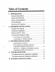
Table of Contents 1. INTRODUCTION pence 1 General Description cocci 1 About Fast Ethernet... 2 About Auto negotiation 3 LED Indicators ..groove nectarine 5 Summary of Features... 5 2. HARDWARE INSTALLATION... 8 Unpack and Inspect 8 Hardware Installation... rise 9 Remove the PC Card 12 Connect the Network Cable... 14 Connecting for Fast Ethernet... 14 Connecting for 10Mbps Ethernet coon. 14 3. SOFTWARE INSTALLATION co.cc 16 Run Installation Director coe.
Introduction Thank you for choosing D-Link DEF-650, the value leader among PC-Card Fast Ethernet adapters. This chapter provides a general description of DEF-650 Series features, with a summary of features at the end of the chapter. Installation instructions are given in Chapter 2. General Description The D-Link DEF-650 Series Fast Ethernet PC Card is a credit-card sized Fast-Ethernet adapter for connecting a notebook PC to an IEEE 802.3 or 802.3u Ethernet network.
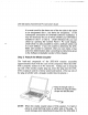
DEF-650 Series Fast Ethernet PC Card User's Guide the media couplet, The DEF-650 requires no per-installation setup —~ simply insert its front end into the notebook PC's PC-Card slot. The DEF-650 is supplied with a media couplet which plugs into the back end (15-pin receptacle) of the DEF-650. The other end of the media couplet has an JR-45 receptacle which receives the network cable. The media couplet features LED indications for linkage an activity states, and for the speed and duplex settings.
DEF-650 Series Fast Ethernet PC Card User's Guide LED Indicators The media couplet features three LED indicators: 1. 10/100 Indicator Steady green indicates Fast Ethernet selected. Dark indicates 10Mbps Ethernet selected. Half /Full Indicator Steady green indicates Full-Duplex selected. Dark indicates Half-Duplex selected. Ln/Act Indicator Steady green indicates that there is good linkage to the network ("Linkage" state, quiescent).
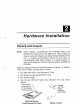
Hardware Installation Unpack and Inspect NOTE: Under ordinary circumstances, the DEF-650 Series Fast Ethernet PC Card will not be affected by static charge as may be received through your body during handling of the unit. In special circus-stances where you may carry an extraordinarily high static charge, it is good practice to reduce the charge by touching a ground before handling the DEF-650. Open the shipping carton and carefully remove all items.
DEF-650 Series Fast Ethernet PC Card User's Guide In the event that any item is missing, or if you find any mismatch or damage, promptly contact your dealer for correction. Hardware Installation Follow these four steps to install the DEF-650 : Step 1 Insert the DEF-650 Under the PCMCIA standard and the corresponding Japanese JIDDA standard, PC Cards may safely be "hot swapped" —— it is not necessary to switch the computer's power off before installing or removing the DEF-650, or any other PC Card.
DEF-850 Series Fast Ethernet PC Card User's Guide It is most usual for the lower one of the two slots in the stack to be designated Slot 1, but there are exceptions. In the subsequent procedure for DEF-650 software installation, it may be necessary for you to know whether your DEF-650 is installed in Slot 1 or Slot 2. Under Windows 95, you can check by opening the Control Panel / PC Card display. Under DOS it is also possible to make a software check, but it is more difficult.
DEF-850 Series Fast Theme PC Card User's Guide is necessary to depress the latch wings of the plug. See the following section, "Remove Theme PC Card.” Step 3 Connect to the Network Medium Make the network connection by running a UTP cable from the supporting hub to your media couplet. Simply plug one end (JR-45 connector) of the cable into an available hub port, and plug the other end (JR-45 connector) into the JR-45 socket of the media couplet.
DFE-650TX Fast Ethernet PC Card User's Guide Interrupt Number Assigned by Plug and Play system Physical Dimensions: 85.6 x 54.0 x 5.0 mm Environment: Storage: -20° to 80°C, (4° to 176° F) Operating: (32° to 131° F) Humidity: 10% to 90% non-condensing Power Consumption: 2.0W PCB Construction: 2 layers Device Drivers* « DIS 2.0 for Banyan + DIS 2.0 for iBM Lan Support/Services « DIS 2.0 for IBM Wrap Server, » DIS 2.0 for Micro Soft Lan Lan Server, and Manager for DOS Communication Manager 1.x « DIS 2.