HIGH-DEFINITION VIDEO PROCESSOR & HUB Owner’s Manual
DVDO BY ANCHOR BAY TECHNOLOGIES, INC. LIMITED WARRANTY WARRANTY VALID ONLY IN THE U.S.A. WARRANTY DVDO by Anchor Bay Technologies, Inc. (DVDO) warrants that products distributed in the U.S.A. that fail to function properly under normal use due to a manufacturing defect when installed and operated according to the owner’s manual enclosed with the unit will be repaired or replaced with a unit of comparable value, at the option of DVDO, without charge to you for parts or actual repair work.
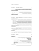
Ta b l e o f C o n t e n t s S e ct i o n 1 – G e tt i n g St a r t e d 2 Introduction 2 Document Conventions 2 Unpacking and Inspection 3 Display Compatibility Requirements 3 Installation Guidelines 4 S e ct i o n 2 – B a s i c O p e r a t i o n 5 Front Panel Overview 5 Rear Panel Overview 5 Video Inputs 6 Video Outputs 6 Audio Inputs 6 Audio Outputs 7 Remote Control Overview 7 Curtain Button 8 Remote Control Battery Installation 8 Menu Navigation 8 Info Screen 8 Power
i S C AN V P 3 0 S e ct i o n 4 – M e n u O p t i o n s 16 Input Select 16 Input Aspect Ratio Control 16 Frame Aspect Ratio 17 Active Aspect Ratio 17 iScan Image Mapping 17 Zoom 18 Pan 18 Borders 18 Presets 19 Front Panel and On-Screen Displays for IAR 20 Input Adjust Control 20 Overscan 20 Line Offset 20 Color Space 20 Input Level 21 VCR Mode 21 Film Mode 21 HDCP Mode 21 Auto Input Priority Selection 21 Audio Input 21 AV Lip Sync 21 Picture Controls 22 Brigh
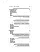
T ABLE OF C ON T EN T S Output Aspect Ratio Control 25 Front Panel and On-Screen Displays for OAR 27 Sync Type 27 Color Space 27 Output Level 27 Framerate Conversion 27 Border Level 28 HDCP Mode 28 Display Profiles 28 Auto Linking of Input and Display Profiles 29 S e ct i o n 5 – A p p e n d i x 30 Non-Volatile Memory Settings 30 System Settings 30 Input/Format Settings 30 Setting up an iScan VP30 Using the Internal Test Patterns and Avia: Guide to Home Theater Calibration DVD
S e ct i o n 1 – G e tt i n g St a r t e d Introduction Thank you for purchasing the iScan VP30 Video Processor powered by ABT. This product delivers a level of quality among the very highest available today. We are especially pleased to bring you ABT’s new Precision Video Scaling II.
Unpacking and Inspection Your iScan VP30 carton should contain the following items: • iScan VP30 Video Processor • Universal 6V@5A AC-to-DC Power Converter • US Power Cord (International Customers, consult your local authorized DVDO reseller) • Remote Control • iScan VP30 Product Guide • iScan VP30 Quick Start Guide • Serial Cable for Software Updates and Automation (1:1) The iScan VP30 uses BNC-style analog connectors and an HDMI digital connector to provide video output signals.
Component video inputs that are not capable of accepting a 480p signal should be labeled ‘480i’ (NTSC) or ‘576i’ (PAL/SECAM).
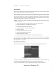
S e ct i o n 2 – B a s i c O p e r a t i o n Front Panel Overview Front Panel Display (FPD) Menu Adjustment Buttons Up Exit EXIT MENU On/Standby Left Down Right Status LED – This displays the current state of the iScan VP30 Off = The unit is in standby mode Red = No signal detected Blue = The unit is processing the signal Green = The unit detects an unsupported signal Analog Video Component 1 (YPbPr or RGB) SDI Input Input Sync 1 On/Standby – This toggles unit power between On and Stand
Video Inputs The iScan VP30 has eleven (11) video inputs and an optional SD-SDI input available (P/N SDI-601A).
While the digital and analog audio inputs can be assigned to any one of the video inputs, the HDMI audio inputs are tied directly to the HDMI video signal connected on the same input. The iScan VP30 accepts digital audio sourced from DVD players, satellite receivers, digital set top boxes, game consoles, or other digital audio devices. These inputs are compatible with most consumer digital audio formats, including CD-Audio (44.1kHz/16 bit LPCM), Dolby Digital, and DTS.
Power/Standby Buttons The iScan VP30 remote has a Power and a Standby button. The Power button always turns the iScan VP30 on and the Standby button always put the unit into Standby mode. Curtain Button The iScan VP30 remote has a Curtain button which allows you to close a ‘curtain’ over the image. This feature is especially useful when an image is paused on a display susceptible to burn-in. Remote Control Battery Installation The remote control for the iScan VP30 requires two AAA batteries.
Output Status Resolution Frame Rate Line Rate Aspect Ratio (Display/Screen) This screen can be helpful during troubleshooting. Power Supply Input The iScan VP30 comes with a 6V@5A AC-to-DC converter power supply, which accepts 100-240 VAC at 50/60Hz. To attach power to the unit: 1. Attach the removable power cord to the external power supply. 2. Plug the removable power cord into a wall outlet or power conditioner, if applicable. 3.
S e ct i o n 3 – S e t u p Initial Set-Up Once you have installed the iScan VP30 into your system, you must properly configure it for the display device being driven. The iScan VP30 is shipped from the factory with the following preset default settings: • Input Select is set to AUTO, to automatically detect an active input in a pre-configured priority.
5. Press the Down button four times. You should see ‘Output Setup / Color Space’ on the FPD. 6. Press the Enter button once. You should see ‘Color Space / YPbPr’ on the FPD. If you don’t, press the Up button once and press Enter. You should see the iScan VP30’s On Screen Display (OSD) on your screen. NOTE: The iScan VP30 cannot output a component signal if the input signal is from a DVI or HDMI source with HDCP. Instead the iScan VP30 outputs a blue screen.
NOTE: Some VCRs and LD players have S-Video outputs. These give an improved picture from these sources. If your LD player or DVR has a digital audio output, ABT recommends you use that connection.
High-Definition Set Top Box or DVR/D-VHS COMPONENT OUT NOTE: Some set top boxes require you to switch the output resolution. This means that if you are watching an HD channel you must manually switch the output resolution to 720p/1080i, or if you are watching an SD channel, you must manually switch the output resolution to 480i or 480p, 480i preferably. If your display only has component or RGBHV inputs, use the component output from your HD source.
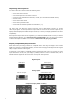
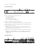
Game Console Game Console Proprietary HDTV AV Pack Optical Audio Component I N P U T SDI INPUT OUTPUT 1 2 INPUT 3 Y (G) Pb (B) H DM I Pr (R) H V Y (G) DC In +6V @5A O U T P U T 4 ANALOG VIDEO I 1 N P U T S 2 POWER Pb (B) 2 SYNC L Pr (R) 1 1 2 2 COMPONENT S-VIDEO OUTPUT INPUT 3 VIDEO R 2 1 1 ANALOG AUDIO INPUT 4 D I G I TA L A U D I O SERIAL PORT Back of iScan VP30 NOTE: Set the game console to output all resolutions (480p, 720p, 1080i) PC PC DVI-D DVI-D DVIHDMI
Audio Operation The iScan VP30 features an audio delay function to exactly match the video delay incurred by the video processing. The iScan VP30 accepts four discrete digital audio inputs, two coaxial (Audio 1, 2) and two optical (Audio 3 and 4) inputs, one analog audio input and four HDMI audio inputs. The locations of the audio inputs are shown on the back panel diagrams earlier in this product guide.
S e ct i o n 4 – M e n u O p t i o n s Input Select There are twelve available inputs on the iScan VP30: • VIDEO 1 Video 1 (Composite) • VIDEO 2 Video 2 (Composite) • S-VIDEO 1 S-Video 1 • S-VIDEO 2 S-Video 2 • COMPONENT 1 Component/RGBs 1 • COMPONENT 2 Component/RGBs 2 • RGBHV RGBHV/Component • HDMI 1 HDMI 1 • HDMI 2 HDMI 2 • HDMI 3 HDMI 3 • HDMI 4 HDMI 4 • AUTO Automatic active input detection and selection • SDI SD-SDI (SDI Vide
The VP30’s menu is exit automatically after 30 seconds of no user interaction. Video input signals are usually classified in the following two ways: • Frame Aspect Ratio • Active Input Aspect Ratio Frame Aspect Ratio Frame Aspect Ratio (FAR) consists of two possible ratios: 4:3 or 16:9. DVD discs encoded in a 16:9 frame are sometimes referred to as anamorphic or enhanced for widescreen TV’s. For example, a non-anamorphic widescreen DVD has a FAR of 4:3.
• When the AAR is equal to the OAR (Output Aspect Ratio), the iScan VP30 supplies no border as shown below: Active Input Area Zoom The Zoom function zooms in on or magnifies the image on your display. The minimum zoom is 100%, (no zooming); the maximum zoom is 150% (zoom magnification factor of 1.5X). Horizontal Zoom Control: Push the Enter button to show the current Zoom setting. Push the Up and Down button to increase or decrease the zooming factor.
Borders are automatically added by the system when the Active Input Aspect Ratio is not the same as the Output Aspect Ratio as explained earlier in this guide. However you can add more borders using the Borders menu. Presets You can specify the Input Aspect Ratio by using the Presets or Manually. Using Presets You can use Presets with either the OSD or the Remote Control Input Aspect Ratio button. Refer to the Preset sub-menu in the Input AR menu for doing this with the OSD.
If you have not customized the aspect ratio, and the current aspect ratio settings are the same as a system defined preset. In this case, the system will not allow you to save the preset setting. Front Panel and On-Screen Displays for IAR The On-Screen Display (OSD) and the Front Panel Display (FPD) allow you to set the Input Aspect Ratio. Input Adjust Control Push the Input Adjust button once to show the current input adjustment function.
Input Level The input level setting allows the user to specify the levels of the input signal, either Video (16-235) or PC (0-255) • Video • PC VCR Mode VCR Mode decouples the output timing completely from the input timing to ensure a stable output from the iScan VP30 for VCR playback especially during trick-play modes (play forward, play reverse, still/pause). • On – Output timing is decoupled from the input timing regardless of Frame Rate settings.
button to display the current additional bias delay setting (default 0). Use the Up or Down button to increase or decrease the delay in milliseconds. NOTE: The total audio delay cannot be less than zero, that is, the iScan cannot have negative audio delay. If you choose to decrease the automatic delay setting by a certain amount, this value could be changed by the iScan in situations where the iScan’s calculated delay plus the specified additional delay results in a value less than zero.
• Auto - Automatic chroma error detection and correction. Use this setting when you don’t know if a source has a CUE problem. Also use this setting for all digital sources which use MPEG2 decoders (DVD players, digital satellite receivers, and so on.) as it will also detect and correct chroma errors created by all sources of this type when the source is encoded as interlaced (also sometimes called Interlaced Chroma Problem, or ICP).
Factory Default The Factory Default option allows you to reset system settings to the factory default. 1- Press either the Up or Down button. The FPD displays ‘No’. 2- Press the same button to switch to ‘Yes’. 3- Confirm this selection by pressing the Enter button.
Information This setting shows information about the system including: Input Status • Video Source • Signal Type • Audio Source • Aspect Ratio (Frame/Active) Output Status • Resolution • Frame Rate • Line Rate • Aspect Ratio (Display/Screen) This screen is helpful during troubleshooting. Analog/Digital (A/D) Push the Down button to show the current output type. Push the Down button again to select the next item on the list shown below.
Output Aspect Ratio Control There are four controls for Output Aspect Ratio (OAR): • Display Aspect Ratio • Screen Aspect Ratio • Image Shift • Underscan The Display Aspect Ratio is the full aspect ratio of the display, normally specified in the display manual. Common display aspect ratios are 4:3 and 16:9. Less common ones are 5:4, 2.35:1 and others. The 37, example below shows a 4:3 projector with a 16:9 screen.
Sync Type The Sync Type option sets the synchronization signal type of the output format. Press the Up or Down button to show the current sync type. Press the same button again to move to the next synctype.
For 60 Hz input sources, the available settings are: • 48Hz Lock source locked 48Hz • 60Hz Lock source locked 60Hz • 72Hz Lock source locked 72Hz • Unlock unlocked If you chose Unlock, press the Enter button again to specify the desired output frame rate. Use the Up or Down button to increase or decrease the frame rate. Press the Output Select button again to exit the menu and complete the output frame rate conversion setting.
• Active Output AR 16:9 • Sync Type H-/V- • Color Space RGB 4:4:4 • Output Level Video • 50Hz input, unlocked to 59.94, 60Hz input – locked. Frame Rate • Border Level • 20 HDCP Mode On Selecting and Saving a Display Profile Use the following procedure to select and save a display profile: 1. Set up the profile by making changes to the output setup menu items. If you make custom settings (such as output timing parameters), they are saved to User. 2.
S e ct i o n 5 – A p p e n d i x Non-Volatile Memory Settings The iScan VP30 stores a variety of user settings in non-volatile memory. Non-volatile memory retains its contents when power is lost. There is one group of system settings and one group of user settings. System Settings Table 2. shows System settings. Table 2.
26 SDI 576i (PAL/SECAM 27 HDMI 1 480i (NTSC) 28 HDMI 1 576i (PAL/SECAM) 29 HDMI 1 480p (NTSC) 30 HDMI 1 576p (PAL/SECAM) 31 HDMI 1 720p (ATSC) 32 HDMI 1 1080i (ATSC) 33 HDMI 1 VGA 34 HDMI 1 SVGA 35 HDMI 1 XGA 36 HDMI 1 SXGA 37 HDMI 2 480i (NTSC) 38 HDMI 2 576i (PAL/SECAM) 39 HDMI 2 480p (NTSC) 40 HDMI 2 576p (PAL/SECAM) 41 HDMI 2 720p (ATSC) 42 HDMI 2 1080i (ATSC) 43 HDMI 2 VGA 44 HDMI 2 SVGA 45 HDMI 2 XGA 46 HDMI 2 SXGA 47 HDMI 3 480i (NTSC)
User Preset Frame AR Active Input AR Pre-defined or User AR User AR Hor. Zoom Hor. Zoom Vert. Zoom Vert. Zoom Hor. Pan Hor. Pan Vert. Pan Vert. Pan Hor. Borders Hor. Borders Vert. Borders Vert. Borders There is only one set of presets (Preset 1 through Preset 4) for the whole system. However the User Preset is per input and per format.
Even though the specifications indicate that this 50” plasma has a native resolution of 1366x768, ABT has found that most plasmas with this stated resolution actually have a 1360x768 native resolution. Most other displays do specify the correct native resolution; this display is an exception. Below are several different popular display technologies and their most likely native resolutions.
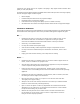
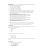
Frame/Geometry Test Pattern Displayed Correctly (Image B) When this test pattern is displayed correctly, it should look like this, with a one-pixel wide white border around the edge of the screen: Frame/Geometry Test Pattern (Image C) As shown in image C, the test pattern is almost displayed correctly. You can see the 1-pixel wide white border on the top, bottom and left side of the image but not on the right side of the image.
When this test pattern is displayed incorrectly, the resulting image does not look like a fine checkerboard and may have irregular patterns. When this is the case, the chosen output resolution may not be the native resolution of your display or your display may scale all input signals even if the input resolution is already at native resolution. Check to make sure that the output resolution selected on the iScan is the correct output resolution for your display.
One is 4 IRE below black (blacker-than-black), one is 1 IRE above black, and the third is 2 IRE above black. Embedded in the white blocks are 3 bars. One is 1 IRE above white (whiter-then-white), one is 1 IRE below white, and the third is 2 IRE below white. The bottom two blocks differ slightly from these levels. For the bottom two blocks, the blacker-than-black is at the lowest possible luma level and the whiter-than-white bar is at the highest possible luma level.
CRT Display Calibration To get the best picture from your CRT-based display make sure that the red, blue and green signals are converged properly. To assist in converging these three signals ABT has included two test patterns. In addition to convergence, make sure that the focus is optimally adjusted. ABT has included one test pattern designed specifically for this application. On some displays, these settings may not be available unless you get into the service menu.
Use the ‘Full Bars’ test pattern in conjunction with the ‘H-Clr7 Bars75’ internal test pattern from the iScan. Use the ‘Full 100 Bars’ with the ‘H-Clr7 Bars100’ internal test pattern. Record Your Settings Once you have set up your iScan, ABT recommends that you record your settings on the installation worksheet which can be reprinted from the DVDO website at http://www.dvdo.com/faq/faq_pro_man.php. Troubleshooting 1. Problem: My iScan VP30 shows an error message.
5. Problem: The Green status LED blinks on the front panel of the iScan VP30. The LED on the iScan VP30 blinks green when it is passing a copy protected signal to a non-HDCP display. If your display is not HDCP compliant, then the image won’t be displayed. Use component connections from your source to your iScan VP30 instead. 6. Problem: Will I lose the settings on my iScan VP30 if I update the software version? Currently, the iScan VP30 may lose its settings when a software update is performed.
Preset 4 User Save User to Preset 1 No Yes Preset 2 No Yes Preset 3 No Yes Preset 4 No Yes Input Adjust Overscan Range: 0-20 Line Offset Range: 0-30 Color Space RGB YPbPr YCbCr 4:2:2 YCbCr 4:4:4 Auto Input Level Video PC VCR Mode Off On Auto Film Mode Off Film Bias Auto HDCP Mode Off On Auto Priority Range: 1-12/Off Audio Input Off Audio 1 Audio 2 Audio 3 Audio 4 Stereo HDMI AV Lipsync Range: 0-200 Picture Control Brightness Range: -50-50 Contrast Range: -50-50 Saturation Range: -50-50 Hue Range: -50-50 Sha
CUE Correction Off On Auto Configuration Test Patterns Frame/Geometry Checkerboard Vertical Lines Horizontal Lines Judder Brightness/Contrast Color8 Bars75 Color8 Bars100 Gray Ramp Window IRE10 Window IRE20 Window IRE30 Window IRE40 Window IRE50 Window IRE60 Window IRE70 Window IRE80 Window IRE90 Window IRE100 Xhatch Coarse Xhatch Fine Focus H-Clr7 Bars75 H-Clr7 Bars100 H-Clr8 Bars75 H-Clr8 Bars100 Auto Standby Active Range: 0-3 Reduced Range: 0-3 User Mode Normal Advanced Serial Port Rate 4800 9600 14400 1
1080i-60 1080p-50 1080p-60 640x480 (VGA) 800x600 (SVGA) 1024x768 (XGA) 1280x1024 (SXGA) 852x480 852x576 1366x768 1280x768 1024x1024 1024x852 1024x576 848x600 1365x1024 1400x1050 1400x788 960x540 1280x960 1440x960 1440x1152 User Horizontal Shift Range: Horizontal Size Range: Horizontal Front Porch Range: Horizontal Sync Range: Horizontal Back Porch Range: Horizontal Total Range: Vertical Shift Range: Vertical Size Range: Vertical Front Porch Range: Vertical Sync Range: Vertical Back Porch Range: Vertical Tot
Range: -30-30 Underscan Range: 0-100 Sync Type Bi-Level Tri-Level Composite H+/V+ H+/VH-/V+ H-/VColor Space RGB YPbPr YCbCr 4:2:2 YCbCr 4:4:4 Output Level Video PC Framerate 50Hz 50Hz Lock 75Hz Lock Unlock Range: 25-120 60Hz 48Hz Lock 60Hz Lock 72Hz Lock Unlock Range: 24-120 Border Level Range: 0-100 HDCP Mode Off On Display Profile Select Profile 1 Profile 2 Profile 3 Profile 4 Save Profile 1 No Yes Profile 2 No Yes Profile 3 No Yes Profile 4 No Yes Auto Off On 43
Index L A active input aspect radio (AIAR) analog inputs audio connections 17 6 audio delay function 15 audio input function 21 audio inputs line offset function 6 M menu navigation menu options auto input priority selection function 21 N auto standby 23 non-volatile memory AV lip sync 21 8 border level setting 28 borders function 18 brightness 22 26 output setup 28 overscan function 20 P 18 22 22 picture controls color space 20 power supply 3 complete menu tree 39 c
DVDO by Anchor Bay Technologies, Inc. 300 Orchard City Drive, Mailstop 131 Campbell, CA 95008 USA Tel: 866-423-DVDO (3836) Fax: 408-379-3845 www.dvdo.com Customer Support Tel: 866-423-DVDO (3836) Extension 333 help@dvdo.