UK Intruder alarm panel Terxon MX – Operating instructions Operating instructions Perfect Security for home and office These operating instructions are an important product accessory. They contain important installation and operation information. Bear this in mind if you pass the product on to others. Store these instructions in a safe place for future reference. For a list of contents with page numbers, see page 3.
1 UK Introduction Dear Customer, thank you for purchasing the Burglar Alarm Panel Terxon MX. You have purchased a product that has been designed and constructed according to the state-of-theart, which complies with the current standards of domestic and European regulations. The CE has been proven and all related certifications are available from the manufacturer (www.abus-sc.eu) upon request.
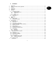
Contents 1 2 3 4 5 6 Introduction........................................................................................................................................2 Usage in accordance with regulations ..............................................................................................2 Contents ............................................................................................................................................3 Precautions.........................................
Precautions !WARNING! UK !ATTENTION! To avoid fire and injury, please observe the following: Please observe the following regulations to ensure trouble-free operation of your device. • Securely fasten the device at a dry location in the building. • The alarm centre is supplied with 12V DC power by means of the internal transformer. • Ensure sufficient air circulation for the alarm centre. • Do not expose the device to temperatures less than -10°C or more than 55°C.
Control unit Additional buttons (see programming menu “87 Control Unit Alarm”): 1 & 3: Press simultaneously to trigger a panic alarm on the control unit. 4 & 6: Press simultaneously to trigger a medical emergency alarm on the control unit. 7 & 9: Press simultaneously to trigger a fire alarm on the control unit. Point 1 2 3 4 5 6 7 8 Description The LED lights constantly if the there is a fault in the telephone line. The LED lights constantly if the system has a fault and must be checked.
6.1 UK Exit delay If the exit delay variant is programmed, you now see the following on the LCD display: Activation Complete activation The alarm system is usually completely activated if you intend to leave the object completely unattended. The alarm centre can be activated only if all zones are ready – i.e., all windows and doors are closed. There are two ways of completely activating the alarm system via the control unit (another way is via a key switch, see page 8): 1.
Close the open zones and activate the alarm system again. Manual If the manual variant is programmed, you now see the following on the LCD display: If a zone is opened during the delay time, the constant tone is interrupted and you hear a pulsed signal tone. These zones are shown on the LCD display. The zones must be closed within the exit delay time, otherwise there is an internal alarm and the system is not activated. Confirm this alarm by entering a valid user code.
6.2 UK Internal activation 6.3 If you want to monitor only part of your object – e.g., only the contacts of your windows or the ground floor – you can activate the alarm system internally. In the alarm centre’s program mode, you can define zones not to be monitored by internal activation. To activate internal mode B, C or D: Key switch With a key switch, you can activate or deactivate your alarm system with a key instead of a user code.
7 Deacitvation 8 You can deactivate your alarm system at any time (even after an alarm) by entering a valid user code. When you enter the object through an entry/exit zone, the programmed entry delay time starts. You now have to enter your user code within the programmed delay time, otherwise an alarm is triggered when the delay time expires. Proceed as follows: 8.
9 User functions 9.1 A series of functions can be performed via the control unit. Summary of user functions. UK Input User code + Master code +4 User code +5 Master code +6 User code +7 User code +8 User code +9 Blocking zones This enables you to block (hide) individual zones to remove them from surveillance. The zone is blocked once only (for the next active monitoring period – i.e., until the next deactivation) and, if required, must be blocked again the next time you activate the alarm system.
IMPORTANT: Some zone types cannot be blocked. You can only block zones released during the programming of the zone property. Zones that cannot be blocked are displayed with an “X” after the zone number. The control unit shows: 9.2 User code The first user code is also the master code. With this code, you can create further user codes and user names. The alarm system can store up to 16 user codes. All users should have their own codes.
Confirm your input by pressing: . 9.3 The control unit shows: Changing the user name Enter the user name (max. 12 characters) via the keypad. UK If you do not want to change the user name, press the following key: . If you want to change the name, see the section “Changing a name” on page 11. After confirming the input of the user name, you are asked to enter the new user code. The control unit shows: In the following, the zone name “HOFNED” is entered.
The control unit shows: 9.4 Touch-free proximity reader (chip key) Instead of entering a user code, a user can obtain legitimation using a touch-free proximity reader (chip key). Point the chip key at the control unit instead of entering a user code. You can give both the master code and a chip key to any user code. To add a chip key to the system: Hold the chip key in front of the control unit. The control unit now loads the chip key function and confirms successful learning with a double tone.
9.6 nn OK Factory settings loaded EEPROM fault Fire zone nn alarm Fire zone nn reset Fire zone nn reconnected BDTnn code lock BDTnn fault BDTnn connected BDTnn Sabo Event memory The alarm system stores the last 250 events. To read the alarm memory: UK Enter a valid user code. The control unit shows: Press: 5 You can page forwards and backwards in the event memory. Press key 1 to page forwards and key 3 to page backwards. to switch between the event and the date. Press to exit the event memory.
Rauchm. Ala. ZN nn Rauchm. Ala. ZN nn Detector test ZN nn Siren tamper reset Sir. Sabo System auto active System started Sabo ZN nn Sabo ZN nn OK Tech ZN nn alarm Tech ZN nn OK Tel line error Tel line error OK Bnn changed Bnn Bnn deleted Bnn Bnn exit Bnn enter Bnn SYS OK Bnn SYS act Bnn SYS deact Bnn time/date Bnn ZN nn locked Bnn ZN nn unlocked Zone nn has triggered a fire alarm 9.
9.8 UK Switching door chime on/off Your alarm system can be programmed so that some zones trigger a tone when entered. To activate/deactivate the door chime for these zones: 9.9 System tests 9.9.1 Siren test You can test all connected acoustic and visual signalling devices. Proceed as follows: Enter your user code. Enter your user code. The control unit shows: The control unit shows: Press 7. Press 8.
The control unit shows: UK Walk through your alarm system and trigger the sensors. If a sensor is triggered, this is reported acoustically by the control units and the internal alarms. Simultaneously, the control unit shows the zone that was triggered. The control unit shows: If more than one sensor is triggered, the zones are alternately displayed one after the other. After triggering all sensors, end the test by pressing . IMPORTANT: You can end the test at any time by pressing .
2. Press the required partition button. The display shows: 10 Operating a partitioned system UK The installer can program the alarm centre so that it behaves like 4 separate alarm centres. The partitions are called partition A, B, C and D. These can be switched active or inactive independent of each other. Several partitions can be switched active or inactive simultaneously; this is set by the installer. 10.1 3. Press .
10.4 After an alarm 10.5 Blocking zones The method used for blocking zones within the partitioned system has changed. Zones can no longer be blocked as long as the system is active. 10.4.1 Switching off the sirens Every partition can issue an alarm, independent of the other partitions. But not all users have access to all partitions. However, the system allows all users to switch off the sirens after an alarm. 1. Enter your access code (or proximity code key), and press .
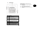
11 System plan This system plan provides information on components installed in your alarm system, their location and functioning, as well as any modifications. The system plan is always a component on the alarm system and should be stored in a safe place.