
Installation User guide

55
UK
27
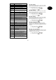
Set 2
This output is activated for a definable
time period (command 170) if the alarm
centre is activated completely (A) or
internally (B), (C) or (D) (command
171).
28
Set 3
This output is activated for a definable
time period (command 170) if the alarm
centre is activated completely (A) or
internally (B), (C) or (D) (command
171).
29
Set 4
This output is activated for a definable
time period (command 170) if the alarm
centre is activated completely (A) or
internally (B), (C) or (D) (command
171).
The output is also activated if a fire or
panic alarm is triggered.
30
Unset 1
This output is activated for a definable
time period (command 170) if the alarm
centre is deactivated completely (A) or
internally (B), (C) or (D) (command
171).
31
Unset 2
This output is activated for a definable
time period (command 170) if the alarm
centre is deactivated completely (A) or
internally (B), (C) or (D) (command
171).
32
Unset 3
This output is activated for a definable
time period (command 170) if the alarm
centre is deactivated completely (A) or
internally (B), (C) or (D) (command
171).
33
Unset 4
This output is activated for a definable
time period (command 170) if the alarm
centre is deactivated completely (A) or
internally (B), (C) or (D) (command
171).
34
Fire
This output is activated if a fire alarm is
triggered. The output remains active
until the alarm is deactivated.
35
PA
This output is activated if a fire alarm is
triggered. The output remains active
until the alarm is deactivated.
4. Confirm your input. On the control unit, enter:
.
5. The control unit acknowledges your input with a
double “beep” tone and shows Installer Mode.
082 Transistor output OP2
To change the behaviour of transistor output OP2 on the
alarm centre PCB:
1. On the control unit, enter:
082
2. The LCD display shows: 082: Strobe
3. Via the keypad, select from the items described
above and enter the function accordingly:
083 Transistor output OP3
To change the behaviour of transistor output OP3 on the
alarm centre PCB:
1. On the control unit, enter:
083
2. The LCD display shows: 083: Set Latch
3. Via the keypad, select from the items described
above and enter the function accordingly:
085 Burglary output
To change the behaviour of the transistor output on
burglar alarms:
1. On the control unit, enter:
085
2. The LCD display shows: 085: Burg=Latched
3. Via the keypad, select from the following items
and press: