Secvest 2Way OPERATING INSTRUCTIONS 1 BOM-No 12000869
Preface Introduction Dear customers, This wireless alarm centre is used to secure your property in combination with detectors and transmitters. Among others, it can be used to protect your company premises, house, garage, summer house or weekend cottage. Many thanks for your purchase of the SECVEST 2Way wireless alarm centre. This device is built according to state-of-the-art technology. It complies with current domestic and European regulations.
14. Resetting the alarm ................................................................................. 16 15. Alarm transmission by telephone............................................................. 17 16. Remote control by telephone ................................................................... 17 17. User menu ............................................................................................... 18 18. Settings in the user menu .........................................................
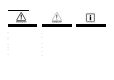
3. Safety information !WARNING! !Caution! To avoid fire and injury, please note the following: Please observe the following precautionary measures to ensure trouble-free operation of your system. • Securely fasten the device in a dry location in the building. • The alarm centre is supplied with power from the built-in PSU. • Ensure sufficient ventilation for the alarm centre. • The PSU is connected to the 230 V AC domestic mains network over a separate, electrically protected line.
4.
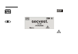
5. Graphic display The graphic display informs you about all events concerning the wireless alarm system. The following is an overview of the different display messages and their meaning: The four black bars stand for the four individual partitions of the wireless alarm system. A letter in the black bar represents the state of the partition (1–4).
6. Activating the wireless alarm system The wireless alarm system can be activated in a variety of ways. The system emits an acoustic message. Depending on whether a partition or the complete system is activated, the message is: “Partition activated” or “Alarm system activated”. 6.1. Fast activation 6.2. User code 6.3. Remote control 6.4. Chip key 6.5. Wireless cylinder Please note that this function can also be deactivated to prevent unauthorised operation of the system.
7. During the delay time Provided no errors that prevent activation have occurred (zone open), the wireless alarm system starts the configured exit delay time. The system emits an acoustic message. Depending on whether a partition or the complete system is activated, the message is: “Partition activated” or “Alarm system activated” During this period, you must leave the premises. A continuous tone sounds during the delay time. This tone is also emitted by the info module (if fitted).
Automatic omission with confirmation System is activated by: • Fast activation • Remote control • Arming station • Chip key • Wireless cylinder The following display is shown: Using the control button, select the item under View to display the error. The following graphic display is shown: The wireless alarm system now shows all zones that are open or have an error. The entry following the zone number directly in front of the zone name is important here.
8.3. Delay time started The following graphic display is shown after entry of the correct user code or immediately after the alarm is acknowledged: The alarm system starts the delay time, but with a pulsed tone instead of a continuous tone. This indicates that one or more zones are still open. Close these zones within the delay time so that a continuous tone is emitted again. If these zones are not closed within the delay time, a local alarm is triggered after the time expires.
9. Following successful activation When the alarm centre is successfully activated (also with automatically omitted zones), an acknowledgement is received after the delay time has expired. This acknowledgement can have different forms: • Acknowledgement tone on the wireless alarm system • Acknowledgement tone on the info module • An SMS from the wireless alarm system • Acknowledgement display on the external wireless siren • Activation of a switch output on the accessory module 9.1.
10. Deactivating the wireless alarm system The wireless alarm system can be deactivated in a variety of ways: • Deactivation of the entire system or a partition with a user code • Deactivation of the entire system or a partition via remote control • Deactivation of the entire system or a partition via a chip key • Deactivation of the entire system or a partition via the wireless cylinder Note: When operating the alarm system with an arming station, please consult the relevant product instructions. 10.1.
11. Activating partitions If the alarm system is set up so that two or more partitions can be monitored independently of each other, these partitions can now be individually activated or deactivated. A user can now activate/deactivate one or more partitions, depending on the user authorisation. If the entire alarm system is activated, each partition is also activated. If the user is authorised to activate one partition only, then this partition can be activated by entering the user code.
12. Internal activation In addition to monitoring one or more partitions (i.e. objects or company departments) separately, the system also has an internal activation option. This type of activation is often used to monitor the exterior of the object when it is still occupied. In this case, specific detectors within the object such as motion sensors are removed from surveillance. The same authorisations apply for internal activation as for any other activation.
13. Alarms The wireless alarm system has three different types of alarm. Depending on the system state (deactivated, internally activated, activated) or triggered alarm zone (technical alarm, panic alarm, burglar alarm, fire alarm), one of the following alarms can be triggered: • • • Local / internal alarm External alarm Silent alarm 13.1. Local / internal alarm 13.2. External alarm 13.3.
“Warning! An alarm has been triggered. A system reset is required.” 14. Resetting the alarm If the alarm system has triggered an alarm (whether local, external or silent), then this must first be acknowledged and then reset. To confirm the alarm, deactivation of the system is sufficient. Follow the instructions described in section 10.
15. Alarm transmission by telephone 16. Remote control by telephone In addition to alarms from sirens and signalling devices, the wireless alarm system can also transmit an alarm via telephone (PSTN, ISDN, GSM). There are two types of alarm transmission by telephone: • Alarm transmission of a digital protocol to a security centre • Alarm transmission of a voice message to any telephone The alarm centre can call you in the event of an alarm.
The alarm centre registers the status of your commands through different tones: 17. User menu Beep Beep, beep Bup Eeh, oh (three times) Pip, pip, pip, pip, pip The user menu is graphically designed to be used almost intuitively. The control buttons are used to navigate around the user menu. = Command accepted = Action carried out = Action failed = Alarm = Reset required Using the arrow keys, you can navigate up and down within a menu item.
18. Settings in the user menu 18.2. Overview of menu items in the user menu 18.1. First steps in the user menu Among other things, the user menu can be used to program the user code, omit zones, record voice messages, read the log, activate control functions and test detectors. Some functions may have been blocked for the user by the installer. The following table lists all possible menu items. In the user mode, proceed as follows: Press the control button under Menu.
If Select was confirmed using the control button, recording begins and the following graphic display is shown: 18.3. Recording voice messages The wireless alarm centre enables the user to record individual voice messages. These voice messages can be listened to and deleted at any time. The system informs the user of the existence of a voice message when the wireless alarm system is deactivated. This allows you to leave messages for other persons.
18.4. Omitting zones 18.5. Installing users If necessary, you can remove zones from surveillance (e.g. if a detector is defective or a zone cannot be closed). As an administrator, you can use your code (master code) to install further users for the wireless alarm system. Up to 50 users can be installed on the system. This menu item is also used for training the remote control, the emergency and panic detectors and the chip key. Select the Omit Zones menu item. Select the User menu item.
18.5.1.1. Changing the user name 18.5.1. Editing users Select the user, then the “Name” menu item. After selecting the Edit User menu item, the user attributes can be edited. Remove the existing name by pressing Delete, then enter a new user name. Enter letters via the keypad. Letter-to-key assignment: Chip key Remote control Pendant Panic transmitter Select the user whose attributes should be edited.
18.5.1.3. Defining partitions 18.5.1.2. Changing the user type User authorisations are defined in this menu. In this way, different users can control different partitions. The settings also refer to the chip key trained for this user. Select the user type: • • The system shows all four partitions. Select the partition whose setting should be changed.
18.5.1.4. Changing the user code 18.5.1.5. Training and removing chip keys, remote controls, pendants and panic transmitters Select the Code menu item. Follow the instructions in the display to train the corresponding components to the wireless alarm system. The following page shows how to train the different components. Components can be removed from a user in the same way as they are assigned. In this case, follow the instructions in the display. Enter the new four-digit code via the keypad.
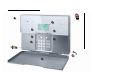
Training the chip key Select Tag. The system prompts you to hold the chip key over the system reader. Hold the chip key over the alarm system as shown in the picture. When the system detects the chip key, it confirms that training was successful. Note: One chip key can be trained for each user. The user code remains active. Training the remote control without panic function (FU5155) Training the remote control with panic function (FU5150) Select Telecommands.
15.5.2. Adding users 15.5.3. Deleting users To add a new user to the wireless alarm system, select the Add User menu item. To delete a user and all user settings (such as remote controls and chip keys), select the Delete User menu item. Select the corresponding user by pressing Delete. You are now guided through the remaining menu items as described in the “Editing users” section. Confirm your entries by pressing OK. The user is then deleted.
If Expanded was confirmed with the control button, the following graphic display is shown: 18.6. Viewing the log This function enables you to read the event log. This log contains the last 250 events together with the date and time. The log cannot be deleted. When the log is full, the oldest event is deleted to make room for a new event (FIFO memory). . To return You can also scroll through the log using the control buttons to the list, select the List menu item. To exit the log, select Back.
System Rearmed U-- Z== Omit Fire Z== Alarm Fire Z== Restore Fire Reset PA Z== Alarm PA Z== Restore U-- System Reset Fire K== Alarm PA K== Alarm Medical K== Alarm Burg Z== Alarm Set Fail Z== Burg Z== Restore Tamper Z== Tamper Z== Restore K== Excess Keys Low Bat Z== Low Bat Z== Rstr RF Jamming RF Jamming Restore RF Sup Fail Z== RF Sup Rstr Z== PSTN Line Fault PLGON Line Fault Entry PSTN Line Restore PLGON Line Restore Comms Fail U-- Remote Download U-- Download Fail AC Fail AC Restore The system has automat
Function Chime 18.7. Additional functions In this menu, a user can switch the functions assigned to them by the installer on and off. Voice Prompts Activity Monitor B’Light Brightness B’Light Always Wall Light Select the Facilities On/Off menu item. Zone Name Prompts Seven menu items are available for selection. 29 Meaning When deactivated, the system emits a signal tone if a door chime detector is triggered. This signal tone can be deactivated here. Activates and deactivates the voice prompt.
Function Siren Loudspeaker Keypad Walk Test Outputs Telecommands Pendants PA Detector Tag 18.8. Test This menu is used to test the different alarm centre functions. Meaning Tests local alarms on the system and external sirens. Tests the loudspeaker function. Tests the keypad function. Tests the functions of the individual zones. Tests the wired and wireless outputs. Tests the remote control (telecommand) functions. Tests the social care transmitter (pendant) functions. Tests the panic detector functions.
Outputs 18.9. System configuration A list of all outputs installed on the system is shown on the display. Select the output to be tested. Press Done to end the test. IMPORTANT: Ensure that nobody attempts to activate the WAM using a remote control or social care transmitter during the test. When the test is ended, check whether the output has the required status. This menu is used to change individual system settings, such as date and time, outputs and remote controls.
Function Meaning Set Date & Time Select this point to enter the date and time of the wireless alarm system. Edit Outputs Select this point to change the times of the manual output. The manual output is activated at the first time entered and deactivated at the second. Note: Outputs can be switched on and off using a suitable remote control or by selecting the “Outputs On/Off” user menu. Telecommands About Comms Additionally, the following alarm centre information is displayed.
18.9.1. Week Planner Only users with administration rights can install this function. The system should be activated and deactivated according to the time and day of the week. First create a weekly plan of the activation and deactivation times. Each day, up to 5 data records can be programmed for activation (start) and 5 data records can be programmed for deactivation (end).
18.9.2. Activation / deactivation of the week planner Access the user menu using the administrator code (default = 1234) and create a week planner. Æ Access the menu and enter your access code. Æ In the System Config menu, select the Auto Set/Unset menu item. Set (activated) Deactivation Activation Y Activation N X Select Y for activation. 18.9.3. Selecting the weekday Monday Time P1 00:00 00:00 01:00 02:00 Æ 03:00 Select the weekday in the week planner.
18.9.4. Auto Set Select the time for Auto Set (00:00). Monday Time P1 00:00 00:00 P3 Tuesday P4 P1 Data record Activation 01:00 Æ P2 02:00 Select data record 1. 03:00 S 04:00 05:00 06:00 07:00 Æ Select activated Y 07:20 08:00 Select the activation time. 09:00 10:00 11:00 12:00 13:00 Æ Set the hour, then press Next to set the minutes and confirm with OK. 14:00 15:00 16:00 17:00 18:00 Æ Select the “Partitions” menu item, then change the partitions to Y or N.
18.9.5. Auto Unset Monday Select the time for the Auto Unset (07:20). Time P1 00:00 00:00 P2 P3 Tuesday P4 P1 01:00 02:00 Æ 03:00 Select data record 1. S 04:00 05:00 06:00 07:00 08:00 Æ Select activated Y 07:20 09:00 Select the activation time. 10:00 11:00 12:00 13:00 14:00 Æ Set the hour, then press Next to set the minutes and confirm with OK. 15:00 16:00 17:00 18:00 Æ Select the “Partitions” menu item, then change the partitions to Y or N.
18.9.6. Internal and external activation In this example, partition 1 is switched from internal activation (external perimeter protection) to external activation (completely activated). The system should have external perimeter protection from 18:00 onwards and a complete activation from 20:00 onwards. The change from internal to external activation cannot be made without an interruption of < 1 minute (e.g. 19:59 Æ 20:00).
18.9.6. Activating and deactivating data records To deactivate a data record (time period), make changes in the AUTO SET menu. In AUTO UNSET, change Set to N.
18.10. Follow Me 18.11. Outputs On/Off This menu is used for entering the follow me number. This number is dialled to send a voice message to a telephone of your choice in the event of an alarm. Apart from the follow me number, up to four other telephone numbers can be dialled. These can only be changed in the installer menu. The follow me number can also be changed in the user menu. This menu is used to activate or deactivate individual outputs manually.
19. Error displays 18.12. Telephone Call There are several errors that can occur during normal system operation. These errors do not immediately trigger an alarm or prevent system activation. All errors should be cleared immediately by the user or reported to the installer as they indicate a malfunction. Errors and error-clearing measures are entered in the event log.
19.1. Errors, meanings, causes and suggested solutions Displayed error AC Fail WAM__PSU Fail Batt Low Meaning The 230 V AC system power supply is missing. 230 V AC power supply is missing in the accessory module. No battery power supply to the system. Possible causes • The main fuse of the PSU on the wireless alarm system is not fitted correctly or is defective. Suggested solutions • Replace the main fuse with one of the same rating. • Check that the fuse is correctly fitted.
Displayed error Low Batt Z__ WAM__ SUP Fail Meaning No battery power supply in zone __. Supervision signal from the accessory module has failed. Possible causes • The battery capacity in the detector of zone __ is almost exhausted. • The accessory module outside the wireless range of the system. Suggested solutions • Change the detector battery within 14 days. • • • Zone Supervision Faults Jamming PSTN Line Fault Supervision signal from detector of zone __ has failed.
20. Declaration of conformity The declaration of conformity to the applicable guidelines has been made available and signed by Security Center management. It is available under www.abus-sc.eu. 21.
Amendments to the operating manual (UK) Secvest 2WAY FU8006 S/W ≥ 5.04.
1. Preface Dear customers, We constantly develop our product range in order to provide our customers with optimal products incorporating state-of-the-art technology. The new software release for the Secvest 2WAY includes optimised workflows and an extended function range. These improvements can be found in the following document. 2. Software status (01.08.2009) The information as detailed below can be found under the “Installer Menu” Æ “About Panel” menu item. Main S/W: Part No.
3. New menu items in user menu 3.1. Secvest Key 2WAY wireless cylinder, item no. FU59xx • Testing User Menu Æ Testing Æ Secvest Key Select the corresponding Secvest Key 2WAY (Door Lock 1, Door Lock 2, Door Lock 3 or Door Lock 4). The wireless cylinder functions can be tested here. “Unlocked” is shown on the Secvest 2WAY display when the door is unlocked. “Locked” is shown when the button on the Secvest Key 2WAY wireless cylinder is pressed and the door is then locked.
3.2. FU8100 wireless remote control User Menu Æ System Config Æ Telecommands Æ 2 Way Instant Set Æ 2 Way Instant Set Y 2 Way Instant Set N • • • “Y” (yes) is the default factory setting. The alarm centre is activated immediately when the FU8100 remote control is pressed.