ABUS WIRELESS ALARM SYSTEM INSTALLATION INSTRUCTION These installation instructions are an important product accessory. They contain important installation and operation information. Bear this in mind if you pass the product on to others. Store these installation instructions in a safe place for future reference. For a list of contents with page numbers, see page 3. For brief instructions of starting up the ABUS wireless alarm package, see page 10-86.
5INWSAIMABEN-C ABUS WIRELESS ALARM SYSTEM These installation instructions are published by ABUS Security-Center GmbH & Co. KG, Linker Kreuthweg 5, D-86444 Affing/Mühlhausen. All rights including translation reserved. Reproductions of all kinds – e.g. photocopy, microfilm, or storage in computer systems – require the express written permission of the publisher. Reprinting prohibited, even in part. These operating and installation instructions correspond to the state of the art at the time of printing.
Contents Chapter 1 Usage in accordance with regulations ................................................................................................................................... 1-5 Chapter 2 Safety information .................................................................................................................................................................. 2-6 Chapter 3 Introduction to the ABUS wireless alarm system ...................................................................
7.5.2 7.5.3 7.5.4 7.5.5 2 3 4 5 Partition ......................................................................................................................................................................... 7-56 Grand Master ................................................................................................................................................................ 7-56 Installer ........................................................................................................
Chapter 1 Usage in accordance with regulations The ABUS wireless alarm system is used for protecting flats and homes and small to medium business objects. If the wireless alarm system and its accessories are installed properly, it alerts you in the case of intrusion, warns you about fires, and calls for help in the event of an emergency. The wireless alarm system and its accessories are designed for protected interior spaces (environment class 1) and must be used there only.
Chapter 2 Safety information For damage caused by non-compliance with these installation instructions, no guarantee claims are possible. No liability can be accepted for resulting damage. In the case of material or personal damage caused by improper operation or non-compliance with the security notes, no liability or guarantee claim can be accepted. For security and authorisation reasons (CE), the unauthorised alteration and/or changing of the alarm system and its components is not permitted.
Chapter 3 Introduction to the ABUS wireless alarm system Congratulations – you made the right choice! The ABUS wireless alarm system offers you professional technology and first-class quality of the specialist for domestic security, packed in a modern, attractive design, and gives you a great feeling of safety and security day after day.
3.2 What is the ABUS wireless alarm system? The ABUS wireless alarm system is an alarm system specially designed and developed for house owners and the owners of small to medium commercial objects. The wireless alarm system ensures 24-hour security with the help of the wireless sensors and detectors installed in your property. Depending on your particular version, the ABUS wireless alarm system triggers burglar alarms, warns you about fire, and calls for help in the event of household emergencies.
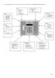
The following graphic gives you an overview of further function properties of your ABUS wireless alarm system: 3-9
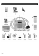
3.5 How can the ABUS wireless alarm system be extended? The ABUS wireless alarm system is a modular, extendable security system.
3.6 CE manufacturer’s declaration EG – KONFORMITÄTSERKLÄRUNG EC – DECLARATION OF CONFIRMITY Wir / We Security-Center GmbH & Co. KG Linker Kreuthweg 5 86444 Mühlhausen (Germany) erklären hiermit, dass das Produkt / herewith declares that the product Typ / Type: auch benannt / also named: Artikel-Nr. / Article No.: ABUS Funkalarmanlage RWABUV868xxA* (*xx=country code) FU9010 konform ist mit den Anforderungen und einschlägigen Bestimmungen der • Richtlinie 1999/5/EC des Europäischen Parlaments vom 9.
Chapter 4 Initial considerations Before starting to install your new ABUS wireless alarm system, please take the time to consider the following. You will find helpful tips for planning your system on the accompanying installation DVD. If you cannot find answers to all your questions, please contact your specialist dealer, who will be pleased to help you. Remember: only a correctly planned and installed alarm system provides maximum security.
4.1 What kinds of security are there? In general, there are three different ways of securing an object: External perimeter surveillance, in which primarily the endangered areas such as the entrance door, terrace door and cellar door as well as ground-floor windows are protected by wireless magnet contacts and wireless glass breakage detectors. The next step is to make sure that all other access areas are protected.
4.3 Where do I install the ABUS wireless alarm system? The ABUS wireless alarm system should be installed in your house near an analogue telephone connector and a 230V power socket – ideally near the centre of the object to ensure good communication with the detectors. You should not install it directly in the entrance area near the entrance door, where it can easily be tampered with. Use a wireless operating panel here.
Chapter 5 Installing the ABUS wireless alarm system Make a sketch of the object or use the architect’s plans. Enter the absolutely necessary wireless detectors defined according to chapter 3. Install the detectors in groups. For example: first magnetic contacts, then motion sensors, then smoke detectors. Or divide your object into areas. For example: living room, kitchen,… or ground floor, cellar,… Name or number the detectors. For a specimen installation plan, see the end of these instructions.
5.2 How do I install the ABUS wireless alarm system? The ABUS wireless alarm system is mounted on the wall in three steps. You need a flat screwdriver to open the casing. A batterypowered screwdriver is best suited for drilling the holes for the fixing screws. You can then use this screwdriver to screw the fixing screws into the wall. Proceed as follows when installing the ABUS wireless alarm system: 5.2.1 Preparing the base plate • • Loosen the casing screw in the middle of the base.
5.2.3 Fixing the faceplate Before fixing the faceplate, first read the following sections (up to page 5-20) and then return here. The preceding sections are not needed for every installation. When carrying out the following, make sure that the voltage is disconnected for all connection work. Both the power adapter and the standby batteries must be disconnected. Before fixing the faceplate, the following installation work should be complete.
5.5 How do I connect the other contacts in the ABUS wireless alarm system? 5.5.1 Connecting a wired sounder The ABUS wireless alarm system is fitted with a built-in sounder. If required, an external sounder or piezo sounder can be connected to alert inhabitants and neighbours with a loud signal during the alarm. To connect an external sounder: • Connect the external cables to the sounder clamps (+ Bell) (Bell -).
NOTE: 1. You can connect external equipment to clamp N.O instead of to clamp N.C. If you connect to clamp NC (normally closed), the circuit between the system and an external device is closed. If the switch output is activated, the system interrupts the circuit and the connected device is switched off. 2. If you connect to clamp NO (normally open), the circuit between the system and an external device is interrupted.
5.6 How are the standby batteries used? The ABUS alarm system is equipped with 6 standby batteries that maintain operation during a power failure. There are two types of battery: Rechargeable: Size AA, 1.2 V DC cells Not rechargeable: Size AA, 1.5 V DC alkaline ! IMPORTANT NOTE: The batteries supplied by Security-Center are rechargeable Nickel Cadmium cells with 1.2 V 800m AAA batteries. Do not attempt to use a different type of rechargeable battery.
5.7 What are the effects of the different jumper settings? The PC board of the ABUS wireless alarm system is fitted with internal jumpers. Configure the jumpers according to the function required as shown in this table: Jumpers on the mainboard Position Function The J9 jumper of the ABUS wireless alarm system is used for restoring the default factory settings of your alarm system. To restore the factory settings, plug the jumper plug on to both pins of the jumper.
Chapter 6 Programming the ABUS wireless alarm system There are several ways of programming your ABUS wireless alarm system: • At the alarm system using the keypad • At the alarm system using the PC software • Remotely, using a telephone link and PC software 6-22
Chapter 7 Settings in installer menu This chapter describes the options and features of the installer menu of your ABUS wireless alarm system. The following is an overview of the main menu options according to their sequence in the installer menu: 1 2 3 4 5 6 7 8 9 0 System, page 7-24 Zones, page 7-36 Outputs, page 7-47 Codes, page 7-53 Dialer, page 7-59 Not active Key-fobs, page 7-67 Keypads, page 7-70 Sounder, page 7-70 Exit, page 7-71 7.
7.2 1 System Under System, you make settings that affect the entire system.
Timers: Quick-Key 1 1 Parameter Default Range Exit/Entry delay 2 2 Exit and entry delay times of Group 2. Make these settings as for Group 1. 1 1 2 1 Entry delay 2 45 seconds 1-255 seconds 45 seconds 1-255 seconds 03 minutes 01-90 minutes Entry delay time for Group 2. 1 1 2 2 Exit delay 2 Exit delay time for Group 2. 1 1 3 Bell Timeout Duration of external sounder(s) during an alarm NOTE: In some countries, the duration of the external sounder must be limited to 3 minutes.
System Control: Quick-Key 1 2 01 Parameter Default Range Quick arm YES YES/NO YES: NO: 1 2 02 Quick UO YES: NO: 1 2 03 2 04 2 05 NO: 1 2 06 NO: 1 2 07 1 1 2 2 08 09 10 YES/NO YES/NO The following signals are emitted by the external sounder to acknowledge whether you have successfully activated/deactivated the system: • One tone means that the system is activated. • Two tones mean that the system is deactivated.
System Control: Quick-Key 1 2 11 Parameter Default Range Buzzer Bell NO YES/NO YES: NO: 1 2 12 Fire Temporal Pattern YES: NO: 1 2 13 NO: 2 14 YES YES/NO The fire signals of the internal and external sounders are three increasing alarm tones followed by a pause. The fire signals of the internal and external sounders are two seconds of continuous tone followed by two seconds’ pause.
System Control: Quick-Key 1 2 20 Parameter Default Range Pager NO YES/NO Enables alphanumeric output of system events on a pager. The number of the pager must be programmed like a Follow-Me number. YES: For the activated/deactivated event and the alarm event, the system sends information to the pager. NO: The system transmits no events to pagers. 1 2 21 Arm Pre-Warning YES: NO: 1 2 22 Low Battery Arm YES: 2 23 Eng.
System Control: Quick-Key 1 2 29 Parameter Default Range Global Follower NO YES/NO YES: NO: 1 2 30 Specifies that all zones (that are programmed to follow an exit/entry delay time) follow the exit/entry delay time of ALL activated areas – i.e., that the system is not activated until after expiry of the longest exit delay time. Specifies that all zones (that are programmed to follow an exit/entry delay time) will only follow an exit/entry delay time of the area for which they are defined.
1 3 7.2.3 Receiver Under Receiver, you can make settings that control the radio receiver of your ABUS wireless alarm system. To access the Receivers menu option: 1. Select the main menu System as described on page 7-24. 2. In the System menu, press 3 to go to the Receivers menu option. You see the following on the display: 3.
Receiver: Quick-Key 1 3 4 Parameter Default Range Delete detectors Deletes all trained wireless detectors simultaneously. To delete the wireless detectors, . To exit this menu option without deleting detectors, confirm the setting by pressing press . NOTES: If the J9 jumper was placed on both pins, this menu appears first in the installer menu. 1 4 7.2.4 Set Clock Under Set Clock, you set the system date and time. To access the Set Clock menu: 1.
1 5 7.2.5 Labels Under System Label, you name the system and areas 1, 2 and 3, and change default names. To enter a new name: Use the buttons of your ABUS wireless alarm system to enter the letters as shown in the table below. When you press a specific button, you scroll backwards and forwards through the characters. The ABUS wireless alarm system permits a total of 75 characters for a name (letters, numbers and symbols).
System Label: Quick-Key 1 5 2 1 5 4 to Menu option Default Selection Partitions 1 – 3 Partitions 1–3 Any 12 characters Changes the display for partitions 1 to 3. Example: The example below shows how to change the name of partition 1 to “Buero” To assign the label “Buero” to partition 1: 1. 2. Press Press 2 1 for partition 1. three times until the letter B appears on the display and then press once to move the cursor to the right. 3.
Tamper Sound: Quick-Key 1 6 Parameter Default Range Speaker Volume 2 Adjusts the volume of the integrated sounder in the event of an alarm and for acknowledgement. 1 6 2 1 Alarm 5 0 to 5 If you confirm this menu option, the sounder is activated briefly at the volume defined. You can adjust the volume with buttons 0 to 5. The setting 0 deactivates the sounder, and 5 is the loudest setting.
1 9 7.2.9 Version The Version menu shows the current version of the alarm system. To access the Version menu: 1. Select the main menu System as described on page 7-24. 9 to get to the Version menu option. 2. In the System menu, press The version of the system with the checksum number of the software is displayed.
7.3 2 Zones The Zones menu enables you to train wireless detectors for the system, program zone types, and define zone dependencies. This is an overview of the menu options according to their sequence in the Zones menu: 2 1 2 2 2 3 Testing, page 7-44 2 4 Editing, page 7-45 2 5 Allocation, page 7-36 Parameters, page 7-37 Crossing, page 7-46 To access the Zones menu: In the installer menu, press Then press 2 or press or until you find the number of the Zones [2] menu option. .
2 1 ZZ Supervision 4 Select whether a zone is to be monitored for regular reporting by the detectors to the alarm system. Set the monitoring time in the System menu under Timers. If surveillance is active for the detector and the detector does not report in the defined time, an alarm is triggered. Select [Y] YES or [N] NO. To change the display, press . To confirm, press . 2 2 7.3.2 Parameters Under Parameters, you can make settings for programming properties of the zones.
Parameter Quick-Key Parameter Default Range Zone termination A wired zone is monitored using a weak electric current. The electric current is defined by the resistor used. You can terminate a zone as follows: • N/C: (= normally closed) a zone termination is not necessary. It is important to use detectors that open the circuit in the event of an alarm. • EOL: (= single resistor) a zone termination with a resistor (2.2kOhm / red, red, red, gold) is required.
Parameter Quick-Key 2 2 Parameter Default Range Zone Partition 3 Partitions 1–3 Under Partition, you assign zones to different areas. This is necessary in larger systems to distinguish, for example, between the commercial area (shop) and the private area (home), when both are monitored by the ABUS wireless alarm system. Under Parameters, press appears on the display: 3 to access the Partition menu option. The following Enter a two-digit zone number and press .
Parameter Quick-Key 2 2 4 Parameter ZZ + Default Exit/Entry 1 Range Armed/internal 01 A zone programmed as Exit/Entry 1 must not be opened during the exit delay time without an alarm being triggered. However, the zone must be closed before the exit delay time expires. If the zone is opened when the alarm system is active, the entry delay time of Group 1 (to be programmed under System/Timers) is started. The area of the wireless alarm system must be deactivated in this time.
Parameter Quick-Key 2 2 4 Parameter ZZ + Default I+Entry follow (Interior+Entry Follower) Range Armed 09 The I+Entry follow zone type is similar to zone type Entry Follower. However, this zone type is not monitored for an internally activated system. 2 2 4 ZZ + I+Instant (Interior+Instant) Armed 10 The I+Instant zone type is similar to zone type Instant. However, this zone type is not monitored for an internally activated system.
Parameter Quick-Key 2 2 4 Parameter ZZ + Default Range Exit Termination 18 A zone with the Exit Termination zone type behaves like a zone with the Exit(OP)/Entry zone type. However, the difference is that an exit delay time is ended immediately if this zone is opened or closed during the exit delay time. When you enter the protected area, the entry delay time of Group 1 starts as usual.
Zone sound Quick-Key 2 2 5 Parameters ZZ + ZZ + Default Range Silent 1 No audible alarm is generated. An alarm is transmitted by telephone only. 2 2 5 Bell Only 2 Activates the external and internal sounders for the defined sounder duration or until a valid user code is entered and the 2 2 5 ZZ + ZZ + key is pressed. Buzzer Only 3 Activates the piezo buzzer of the alarm system.
2 3 7.3.3 Zone Testing Under Testing, you can check the correct functioning of zones. To access the Testing menu: 1. Select the Zones menu as described on page 7-36. 2. In the Zones menu, press 2 3 1 3 to access the Testing menu option. You see the following on the display: Wireless Communication Test Runs a communication test between the wireless detector and the ABUS wireless alarm system. 2 3 2 1 1. Press . You see the following on the display: 2.
2 4 7.3.4 Editing Under Editing, you can copy and delete programmed zones. To access the Editing menu: 1. Select the Zones menu as described on page 7-36. 2. In the Zones menu, press 4 to get to the Editing menu option. You see the following on the display: Editing Quick-Key 2 4 1 Parameter Copy to a zone Copies all settings programmed for a zone (except the zone name). 1 . You see the following on the display: 1. Press 2.
Editing Quick-Key 2 4 Parameter Delete a partition 4 Deletes a selected partition. All zones assigned to this partition are also deleted. 1. 2. 4 Press . Press the cursor keys to select the area you want to delete. 3. Press 4. Press to switch between [Y] YES and [N] NO and press . to exit the program. 2 5 7.3.5 Cross Zone Default: No cross-zone dependency Cross-zone dependency is an ideal function for making a system safer against false alarms.
7. After programming the type of interdependency, press to um define the time interval between 1 and 9 minutes. The menu for programming the time interval opens. 8. Enter the time that can elapse between the triggering of the first and second detectors. If the interval is too big, it is possible that no alarm will be triggered.
7.4 3 Outputs Under Outputs, you program the relay and transistor outputs of the system. You link different system events to the activation of the outputs. The following is an overview of the menu options according to their sequence in the Outputs menu: 3 1 3 2 3 3 Define, page 7-48 Output A, page 7-53 Output B, page 7-53 To access the Outputs menu: In the installer menu, press menu option. Press 3 or press or until you find the number of the Utility Output [3] .
Define Quick-Key 3 1 UO Parameter 1 04 Trouble Follow The switch output is activated if a system fault is detected. It is deactivated as soon as the fault is cleared. 3 1 UO 1 05 Low Battery Follow The switch output is activated if the battery of the ABUS wireless alarm system has insufficient reserve capacity and the voltage falls to 7V.
Define Quick-Key 3 1 UO Parameter 2 08 Duress Follow The switch output is activated if a forced alarm is triggered on the operating panel in one of the selected areas. To deactivate this switch output, see the user menu under Duress Reset ([2] [6]). (This is described in the ABUS User Guide.) 3 1 UO 2 09 Buzzer Follow The switch output is activated if an operating panel activates its buzzer in the selected area(s).
Define Parameter Quick-Key 3 1 UO 2 20 Auto Arm Alarm The switch output is activated if an alarm was activated during the prewarning time during an auto-arm process. 3 1 UO 2 21 Zone Loss Alarm The switch output is activated if a wireless zone is lost. 3 1 UO Follow Zone 3 This menu option lists events for a zone. 3 1 UO 3 1 Zone Follow The switch output is activated if the selected zone is triggered. The state of the alarm system is not relevant.
Output mode An output mode has to be set for every output. This table gives an overview of the different output modes: Outputs Quick-Key 1 Parameter Default Range Pulse N/C 05 seconds 01-90 seconds The output is closed in non-activated state. Once activated, it remains open until the set time has elapsed and then resets itself automatically. 1. 2. 2 1 Press followed by . Enter a pulse duration between 1 and 90 seconds. 3. and enter the activation of your choice (ALL or ANY).
Activation/Deactivation If the switch output follows more than one area or zone, you can use different patterns for activating and deactivating the switch output. ALL or ANY. All: ALL areas (or zones) programmed for this switch output must be triggered in order to activate the output. On the other hand, all areas or zones must be inactive in order to deactivate the output. The latter applies only to the outputs Latch N/O and Latch N/C.
7.5 4 Codes Under Codes, you can define user and installer Codes, define authorities, and assign areas. The ABUS wireless alarm system also has the following Codes. Grand Master Code: Used by the system owner. This Code has authority over all others and can only be changed but not deleted. The default is: [1][2][3][4]. Installer Code: This Code is needed for programming the system. The default is: [0][1][3][3]. Sub-Installer Code: This Code can also be used for programming the system.
Authority Levels The Authority Levels menu option contains settings for the following authorities: Grand Master: There is only one Grand Master in the system. The Grand Master can carry out all available user functions. The Grand Master code is defined as PIN code user 00. NOTE: Under System Control, you can define that the Grand Master can change authorities as well as areas permitted for users. See under Grand Master Authority/Partition (press [1] [2] [27]).
4 2 7.5.2 Partition Default: Partition 1 Under Partition, you assign to user PINs partitions for which you have authority. The Grand Master is authorised in all partitions. To access the Partition menu: 1. Select the Codes menu as described on page 7-53. 2 2. Under Codes, press 3. Enter the respective two-digit user code and press 4. Press or to place the cursor under the number specifying the partition to which you want to allocate the code.
4 4 7.5.4 Installer Default: 0133 With the installer PIN, you have access to the installer menu and thus the authority to change all system parameters. The installer code defined in the factory is: [0][1][3][3] ABUS strongly recommends changing the PIN defined in the factory. To access the Installer menu: 1. Select the Code Maintenance menu as described on page 7-53. 4 to access the Installer menu option. You see the following on the 2. Under Code Maintenance, press display: 3.
4 6 7.5.6 Code Length Default: four digits Under Code Length, you can change the number of digits used (4 or 6) for the Grand Master, the Manager and the Master. All other PIN codes (user, Arm Only and maid) use one to six digits. To access the Code Length menu: 1. Select the Code Maintenance menu as described on page 7-53. 6 to access the Code Length menu option. You see the following on 2. Under Code Maintenance, press the display: 3.
7.6 5 Dialer The Dialer menu enables you to transmit alarms as voice text by telephone. In this menu, you also make the settings necessary for programming the system via a modem. Some of the options in this menu cannot be selected since they are not active in this version.
Access Code and ID Quick-Key 5 5 1 Parameter Default Access code 5678 Defines an access code for remote programming. The four-digit access code in the system and the software must be identical. 1. Enter a four-digit access code. This code is stored in the ABUS wireless alarm system. 2. You have to enter the same code in the up/download software for access to this system. 5 5 3. Press 4. Press 1 and enter the four-digit code. to confirm.
Controls Quick-Key 5 6 02 Menu option Default FM Enable NO YES: Enables FM (= Follow Me) transmission. (See also Follow Me, page 7-64.) Enable this option to transmit alarms as voice messages by telephone. Disable this option if the system has no telephone connection, since otherwise a telephone error is reported. NO: No FM transmission is possible. 5 6 03 U/D Enable NO YES: Enables remote dialling of the up/download software by modem.
Controls Quick-Key 5 6 10 Menu option Default Answering Machine Override YES YES: Answering machine override is activated. • The upload/download software calls the ABUS alarm system. • The software hangs up following a ring by the U/D user. • The software calls again within one minute. • The ABUS wireless alarm system is programmed to answer this second call immediately and not forward the call. The function of the number of calls for U/D is deactived.
Dialer: Parameter Quick-Key 5 7 4 Parameter 2 Press 5 7 5 5 7 5 Default Range 30 seconds 30 or 60 seconds Wait 9 seconds 2 followed by . Redial wait The number of seconds between a redial of the same number. 1 Wait 30 seconds Press 5 7 5 2 7 followed by 2 followed by Dialing method 6 . Wait 60 seconds Press 5 1 . DTMF DTMF (Touch Tone ®), pulse 20 BPS and pulse 10 BPS Select DTMF (Dual-Tone Multi-Frequency) as the dial method.
Dialer: Parameter Quick-Key 5 7 9 2 Parameter Default Range UD Test Hr:00 Min:00 00-24 hours 00-59 minutes Under this option, enter the following: The time for the periodic test call (in 24-hour format) and the frequency interval. To program the test time and the intervals for periodic transmissions: 7 0 . You see the following on the display: Press 2. 3. Enter the time in 24-hour format. Define the frequency interval (D) according to the table below.
7.6.5 5 9 Follow Me (FM) Under this menu option, you define the forwarding of an alarm as a voice text to a telephone or a security service. In the event of an alarm, the ABUS wireless alarm system calls the programmed FM numbers and transmits the alarm message according to the event. There are two variants of this FM feature: • Standard Phone Call: The ABUS wireless alarm system transmits the alarm message as a voice text to programmed numbers, depending on the event.
Follow-Me Quick-Key 5 9 2 Parameter Default Events restore Defines whether a new call is made if the event (from section 5.9.1) is reset. Press or to select an event and press event is to be transmitted by phone: [Y] YES or [N] NO. [01] Intruder Y [02] Tamper N [03] AC Off N [04] Wireless Lost N [05] Wireless Low Battery N [06] Bell Trouble N [07] Low Battery N [08] Wireless Jamming N [09] BUS Trouble N After defining all events, press press 7-66 .
7.7 7 Key-fobs Under key-fobs, you learn how to train up to eight 4-button key-fobs with rolling code to work with the ABUS wireless alarm system. With the wireless key-fob/remote control, you can activate/deactivate the system, trigger a panic alarm, and control a switch output.
7 2 7.7.2 Parameters Under Parameters, you program the function and the keys of the remote control. The four buttons of the remote control can be adapted to individual requirements. To access the Parameters menu: 1. Select the Key-fob menu as described on page 8-68. 2 2. Under Key-fob, press to access the Parameters menu option. You see the following on the display: 3. Select the remote control you want to reprogram and press .
If you select the switch output function and confirm it with or Select a utility output with , you see the following on the display: and confirm your selection with . 10. The system changes automatically to the next button and the you see the following on the display: 11. For button 4 (large button), you can choose between the following functions: None: The button is not activated (default). Arm: The button activates all previously selected areas.
7.8 8 Keypads Under Keypads, you can assign two operating panels to the ABUS wireless alarm system. The following is an overview of the menu options according to their sequence in the Keypads menu: 8 1 Allocation, page 7-77 8 2 Communication test, page 7-77 To access the Keypads menu: • In the installer menu, select Press 8 or press or to access the corresponding menu option. .
8 2 7.8.2 Communication Test Under Communication Test you test the radio communication between your wireless operating panel and the system. To access the Communication test menu: 1. Select the Keypads menu as described above. 2 2. Under Keypads, press display: to access the Communication test menu option. You see the following on the 3. 4. Press or to select the wireless operating panel you want to test. Press the activation button on the wireless operating panel.
7.9 9 Siren Under Siren, you can assign 3 sounders to the ABUS wireless alarm system. You can choose between internal wireless sounders and external wireless sounders. The following is an overview of the menu options according to their sequence in the Siren menu: 9 1 9 2 9 3 9 4 9 5 Allocation, page 8-75 Parameter, page 8-76 Comm.
7. Confirm the Write menu option with a message from the sounder. 8. Insert all batteries in the sounder. Press the Reset key for five seconds. Then press the lid contact of the sounder and keep it pressed until the system receives the signal. You see the following on the display: 9. Press or and your alarm system waits for a signal from your sounder. Send to select whether the sounder is to be monitored or not, and confirm your selection with . The sounder is now ready for operation. 10.
7.9.3 9 3 Communication test Under communication test you test the radio communication between your sounder and the system. To access the communication test menu: 1. Select the Siren menu as described above. 3 2. Under Siren, press display: to access the communication test menu option. You see the following on the 3. Confirm with . The system now searches for the wireless sounders and then shows the signal strength of each sounder on the display.
7.9.5 9 5 Tamper Mute Under Tamper Mute, you can deactivate the tamper function of the sounder for the current programming process. This enables you to open the sounder without triggering a tamper alarm. Enable this function if you want to open the sounder case, for example to change the batteries. To access Tamper Mute menu: 1. Select the Siren menu as described above. 5 to access the Tamper Mute menu. You see the following on the display: 2. Under Siren, press 3. Confirm with .
7.10 0 Exit Programming Under Exit Programming, all your settings in the installer menu are saved and you exit the installer menu. Important: The settings you make in the installer menu are not saved until you exit the installer menu correctly. NOTES: To be able to exit the installer menu, the J9 jumper plug must be plugged on to one pin. To access the Exit Programming menu: 1. 0 or press In the installer menu, press option.
Chapter 8 Programming within the user programming menu This chapter explains an important menu option in the user menu. This menu option is for programming voice messages and conducting a walk test. 8.1 Programming voice messages Your ABUS wireless alarm system can issue system events locally and by telephone using voice messages. This greatly simplifies operating the system and enables remote control of the system by telephone. The voice message menu option is in the user menu.
7 1 8.1.1 Message structure Under Message structure, you define the sequence in which the voice messages are transmitted. To define a message structure: 1. Select the voice message menu as described above. 2. In the voice message menu, press on the display: 1 to access the message structure menu option. You see the following 3. Press to select one of the following structure types.
Voice message: message name Quick-Key Parameter Default Range Recording stops automatically after 10 seconds. If you want to stop recording earlier, press . NOTE: If you do not press as soon as your recording is finished, you may have unwanted noise or a long pause in your message. Press 7 2 2 to exit the menu option. Zone message Press 2 . You see the following on the display: Press or to select a zone and then press The following options are available: . 1 to play the zone announcement.
Message Labels Quick-Key 7 2 3 Parameter Default Range Partition Message Press 3 . You see the following on the display: Press or to select a partition and then press The following options are available: . 1 to play the partition announcement. You hear the Press announcement over the system loudspeaker. Press 2 to record a new text. You see the following on the display: Press and speak your message into the microphone.
Message Labels Quick-Key 7 2 5 Parameter Default Range Macro Message Press 5 . You see the following on the display: Press or to select a macro and then press The following options are available: . 1 to play the macro announcement. You hear the announcement Press over the system loudspeaker. 2 Press to record a new text. You see the following on the display: and speak your message into the microphone.
Voice message: Message test Quick-Key 7 3 1 Parameter Default Range Send message Under this menu option, you can transmit a test message to a previously programmed FM number. To send a test message: 1 . You see the following on the display: 1. Press 2. or to select the FM number to which you Press want to send the test message. You see the following on the display: The ABUS alarm system calls the FM number and you hear the following test message: “Test Message”.
7 4 8.1.4 Local Announcement Messages Under this menu option, you adapt local voice announcements to your requirements. To activate/deactivate local voice announcements: 1. Select the Voice Message menu. 2. In the Voice Message menu, press the display: 3. Press or by pressing 4 to access the Announce msg. menu option.
8.2 Walk test Under the Walk test menu option, you can test your installation. When the system is in walk-test mode, you can trigger detectors without setting off an alarm. The walk test mode can be started in two ways: • Installer PIN • Grand Master PIN NOTE: The difference between a walk test started with an installer PIN and a walk test started with the Grand Master PIN is the way your ABUS alarm system reacts to a tamper message.
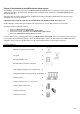
Chapter 9 Accessories for your ABUS wireless alarm system The following is a list of accessories for your ABUS wireless alarm system. Wireless motion detector The wireless motion detector is used for protecting entire rooms. With its infrared element, it can monitor an area of 15 x 15m with an angle of vision of 90°. Pet-immune wireless motion detector The pet-immune wireless motion detector, like the normal wireless motion detector, is used for protecting entire rooms.
Chapter 10 Brief guide This chapter explains the installation steps shown on the DVD for the ABUS wireless alarm package including a smoke detector. After you have taken the installation steps shown in this guide, your ABUS wireless alarm system is completely operational. 10.1 Hardware installation 10.1.1 ABUS wireless alarm system • • • Install the ABUS wireless alarm system in a suitable place in your object. Plug the power supply unit into the AC socket of the wireless alarm system.
10.2 Training the detectors for the ABUS wireless alarm system 10.2.1 Installer menu of the ABUS wireless alarm system • First press the star button, followed by 9, followed by 1. 9 • 1 You are asked to enter the installer PIN code for the installer menu. The default setting is 0133. Enter this installer PIN and confirm your input with the lozenge button. 0 1 3 3 You are now in the installer menu and see the following display: 10.2.2 Allocate detectors • 2 .
10.2.3 Programming zones You do not have to program the zones for the detectors in your package. They are already programmed for you as follows: No.
10.4 Exiting the installer menu All wireless components in the package are now trained. Your ABUS wireless alarm system is almost ready for operation. You just have to enter the date and time and an alarm telephone number for voice text transmission in the event of an alarm. First, exit the installer menu. Proceed as follows: 0 . • Press The display asks if you want to save your data. • Press to confirm.
• • Confirm the menu option phone number 1 with the Enter button. On the system keypad, enter the number with local area code and if necessary a zero for obtaining a dial tone. To program a dial pause, enter A. You program the A with the appears. • • and To change the entered number, press the cursor buttons number you want to change. To delete the entire number, program an E with the entered number with the displayed. • button.
Chapter 11 Example of an installation plan The following table provides an overview of the information your installation plan should contain: Partition 1 Zone number 1 Detector Door and window 1 2 Door and window Zone type Entry/exit Name MC front door Entry/exit MC terrace door contacts contacts 1 3 Motion detector Instant MS living room 1 4 Motion detector Instant MS entrance hall 1 5 Smoke detector Fire SD living room 1 6 Smoke detector Fire SD bedroom 1 7 Smoke detector
Partition Zone number 1 2 3 4 5 6 7 8 9 10 11 12 13 14 15 16 17 18 19 20 21 22 23 24 25 26 27 28 29 30 31 32 33 11-92 Detector Zone type Name
Appendix A: Event Log Messages This appendix provides descriptions of all the Event Log messages(ver 1.2xx) EVENT MESSAGE DESCRIPTION Activate UO=X UO XX activation Actv UO=XX WB=YY UO XX is activated from key-fob YY Alarm Z=XXX Alarm in zone No.
11-94 EVENT MESSAGE DESCRIPTION Forced P=X Partition X is force armed Found Z=XXX Wireless zone found, zone No. XXX Func=XX C=YY Quick key function XX by user YY Home:P=X C=YY Partition X is armed in Stay(Home) mode by user YY Home:P=X WB=YY Partition X is armed in Stay(Home) from key-fob YY Jamming restore Wireless jamming restore Ksw arm:P=X Partition X is armed by keyswitch Ksw disarm:P=X Partition X is disarmed by keyswitch L.
EVENT MESSAGE DESCRIPTION Spec. main KP Special alarm from the WisDom emergency keys Soak fail Z=XXX Zone XXX has failed in the Soak test Start exit P=X Exit time started in partition X Tamper KP=XX Tamper alarm from keypad ID=XX Tamper UO=X Tamper alarm from X10 expander ID=X Tamper Z=XXX Tamper alarm from zone No. XXX Tamper rst KP=XX Keypad XX tamper restore Tamper rst UO=X Tamper alarm restore from X10 expander ID=X Tamper rs Z=XXX Tamper alarm restore on zone No.
11-96