
Specifications


5-15
Chapter 5 Installing the ABUS wireless alarm system
Make a sketch of the object or use the architect’s plans. Enter the absolutely necessary wireless detectors defined according to
chapter 3. Install the detectors in groups. For example: first magnetic contacts, then motion sensors, then smoke detectors. Or
divide your object into areas. For example: living room, kitchen,… or ground floor, cellar,…
Name or number the detectors. For a specimen installation plan, see the end of these instructions. You will need the installation
plan again and again in the course of your activities.
This chapter answers the following questions:
• What is what inside the ABUS wireless alarm system?
• How do I install the ABUS wireless alarm system?
• How do I install the power and telephone connections?
• How do I adjust the contrast of the LCD display?
• How do I connect the other contacts in the ABUS wireless alarm system?
• How are the standby batteries used?
• What are the effects of the different jumper settings?
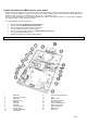
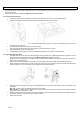
5.1 What is what inside the ABUS wireless alarm system?
The following graphic shows the inner structure of the ABUS wireless alarm system.
1 Base plate 12 Power voltage reset jumper
2 Case tamper opening 13 LED
3 Cable hole 14 Battery jumper
4 Telephone plug 15 Control output jumper
5 Power IN 16 BUS connection
6 Flat cable 17 Internal sounder/buzzer
7 Faceplate 18 Main connector block
8 LCD light dimmer 19 Battery case screw
9 Tamper spring 20 Battery case
10 System reset jumper 21 Wall fixing
11 Loudspeaker