
Specifications


Hardware Characteristics
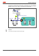
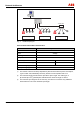
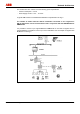
IM/265/7/9/ADD/FF-EN_01 Connection to FOUNDATION Fieldbus 15
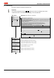
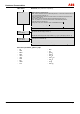
5.4 Structure tree
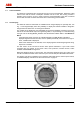
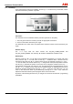
The menu is called up using the mode button "M".
Important
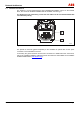
The numbers displayed inversely ( 1 to 9 ) specify the code for the display value. These
numbers are shown on the 2nd line of the display, on the left-hand side.
Main menu Submenu (other parameters / explanations)
EXIT
VIEW
(Temporary display of
display values 1 to
9 )
Output signal in physical unit
(265Dx: Current measured value for differential pressure, or measured value derived from
this, such as flowrate / level and / or:
265Gx:Current measured value of the gauge pressure or measured value derived from
this such as level and / or:
265VS, 265Ax: Current measured value of the absolute pressure and / or:
267JS / Cx, 269JS / Cx: Current measured value of the differential pressure,
In eachcase with user-specific unit.
Corresponds to the "OUT" variable in case of PROFIBUS PA or FF 1 .
Percent value of output signal 2 .
Mass flow / standard volume flow (only for 267Cx, 269Cx) 4 .
Operating volume flow (only for 267Cx, 269Cx) 5 .
Static pressure (only with differential pressure transmitters) 6 .
Process temperature (only with 267JS / Cx, 269JS / Cx, displays the temperature of
the Pt100) 7 .
Pressure / differential pressure 8 .
Sensor temperature 9 .
GET 0 %
Setting with applied pressure (only for 265xx)
GET 100 %
Setting with applied pressure (only for 265xx)
SET 0 %
Setting without applied pressure (only for 265xx)
SET 100 %
Setting without applied pressure (only for 265xx)
SHIFT ZERO
Sensor misalignment / zero correction
OFFSET SHIFT
Parallel shift (only for 265xx)
OUT 0 %
Setting of output variable (only for 265xx)
OUT 100 %
Setting of output variable (only for 265xx)
DAMPING