VGA-Übertragungsystem Installationsanleitung VGA Transmission System Installation Guide Système de transmission VGA Instructions d’installation Sistema di trasmissione Twisted Pair Istruzioni per l'installazione VGA-overdrachtssysteem Installatieaanwijzingen VGA overførselssystem Installations Guide Version 1.
1. Vorwort Sehr geehrte Kundin, sehr geehrter Kunde, wir bedanken uns für den Kauf dieses VGA-Übertragungssystems. Sie haben ein Produkt erworben, das nach dem heutigen Stand der Technik gebaut wurde. Dieses Produkt erfüllt die Anforderungen der geltenden europäischen und nationalen Richtlinien. Die Konformität wurde nachgewiesen, die entsprechenden Erklärungen und Unterlagen sind beim Hersteller hinterlegt.
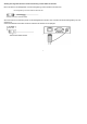
4. Anschlussplan TV8760 135m (max) Empfängermodul Sendermodul Max.
. Anschlussplan TV8760 (Fortsetzung) Sendermodul Rückseite Sendermodul Frontseite Anschlüsse am Sendermodul TO MONITOR/VGA: Eingang für die VGA-Video-Signale RJ-45 Ausgang für die Übertragung des gesamten Videosignal über ein CAT 5 UTP oder STP-Kabel 4
4. Anschlussplan TV8760 (Fortsetzung) Empfängermodul Rückseite Empfängermodul Frontseite Anschlüsse am Empfängermodul RJ-45: Eingang für die Übertragung des gesamten Videosignals über ein CAT 5 UTP oder STP Kabel TO MONITOR/VGA: Ausgangsbuchse für VGA-Signale Achten Sie darauf, dass Sie die Verbindungsleitung möglichst nicht in der Nähe von spannungsführenden Leitungen verlegen, da dies in seltenen Fällen zu Interferenzen (schlechte Bildqualität) führt.
5. Installation Achtung: Die folgenden Hinweise sind nur bei Verwendung von UTP-Kabel zu beachten. DIP-Schalterfunktion: Die DIP-Schalter an der Sender/Empfänger-Rückseite dienen zur Anpassung des Synchronisierungssignals an die UTP-Kabellänge. Die DIP-Schalter-Einstellung kann bei Verwendung von STP-Kabel vernachlässigt werden. Die DIP-Schalter-Einstellung erfolgt in Stufen von 1 - 15, dabei werden aktivierte DIP-Schalter-Nummern addiert (z.B. 2 + 3 = Stufe 5). 1. 2. 3.
Achtung: Die folgenden Hinweise sind bei Verwendung von STP-Kabel zu beachten. Bei RJ-45-Steckern mit Metallgehäuse muss die Erdungsleitung mit dem Gehäuse verbunden sein. Die Erdungsleitung muss dem Gehäuse verbunden sein! Anschluss: STP RJ 45 / Gehäuse: Metal Wenn Sie einen RJ-45-Verbindung-stecker mit Kunststoffgehäuse verwenden, dann verbinden Sie bitte die Erdungsleitung mit einer Schraube mit einem Abstandsbolzen der SUB-D- Buchse am Gehäuse des Senders bzw. Empfängers.
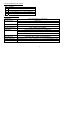
5. RJ-45 PIN-Belegung der TV8760 PIN Funktion 1 R Video (rot): Pin 1 (+), 2 G Video (grün): Pin 4 (+), Pin 5 (-) “balanced” B Video (Blau) Pin 7 (+), Pin 8 (-) “balanced”. 3 4 Pin 2 (-) „balanced“ Horizontale Synchr.: Pin 3, Vertikale Synchr.: Pin 6 6. Technische Daten TV8760 Umgebung Eingangssignal Anwendungen bei: Einfügungsdämpfung Rückflussdämpfung Widerstand Übertragungsdistanz Kabel für RJ-45 Temperaturbereich Maße (HxBxT) VGA, VESA VP&D 1.0, VIP ver 2.0 Video 1Vss Hor. und vert. Synchr.
VGA Transmission System Installation Guide VGA Übertragungsystem Installationsanleitung Système de transmission VGA Instructions d’installation Sistema di trasmissione Twisted Pair Istruzioni per l'installazione VGA-overdrachtssysteem Installatieaanwijzingen VGA overførselssystem Installations Guide Version 1.
1. Preface Dear Customer, Thank you for purchasing this VGA transmission system. This product was designed and built using state-of-the-art technology which complies with the current standards of domestic and European regulations. The CE has been proven and all related certifications are available from the manufacturer upon request. To maintain this status and to guarantee safe operation, it is your obligation to observe these operating instructions.
4. TV8760 connection diagram 135m (max) Receiver module Transmitter module VGA-Display Max. distance via CAT 5 UTP cable 640x480 Pixels (15MHz) 135m 800x600 Pixels (30MHz) 105m 1024x768 Pixels (60Mhz) 75m 1280x1024 Pixels (100MHz) 60m Attention: If you use RJ-45-Jack with metal housing, the shield from the connection cable has to be connected with the metal housing. Using RJ-45-Jack with plastic housing needs essentialy grounding with the housing of the transmitter/receiver.
4.
4. TV8760 connection diagram (continued) Receiver module backside Receiver module frontside Connections at the receiver module RJ-45 female: input transmission of the hole videosignal throgh CAT 5 UTP or STP cable TO MONITOR/VGA: output VGA signal Make sure that you do not lay the connection line near electrical power lines – in rare cases their proximity may lead to interference (poor picture quality).
5. Installation Attention: Please comply with the following instructions if you are using CAT5 UTP cable. DIP switch function: The DIP switches at the back side of transmitter/receiver can be used to adapt the sync signal to the UTP cable length. This setting can be disregarded on using STP cable. The DIP-switch setting can be done in stages from 1 -15. The DIP switch numbers are added, the outcome of this is current stage (e.g. 2 + 3 = stage 5). 1. 2. 3.
Attention: Please comply with the following instructions if you are using CAT5 STP cable. If you use RJ-45-Jack with metal housing, the shield from the connection cable has to be connected with the metal housing. Ground cable: Must touch the metal housing Connector: STP RJ 45 Housing : Metal Using RJ-45-Jack with plastic housing needs essentialy grounding with the housing of the transmitter/receiver. Therefore connect the shielding from the cable with the screw of the D-SUB from the transmission system.
5. RJ-45 PIN-define TV8760 PIN Funktion 1 R Video (red): Pin 1 (+), 2 G Video (green): Pin 4 (+), 3 B Video (Blue) Pin 7 (+), 4 Horizontal Sync.: Pin 3, Pin 2 (-) balanced Pin 5 (-) balanced Pin 8 (-) balanced. Vertical Sync.: Pin 6 6. Technical specifications of TV8760 Environment Input signals Devices Insertion Loss Video Signal Return loss Impedance Transmission distance Cable for RJ-45 Temperature Dimensions (HxWxD) VGA, VESA VP&D 1.0, VIP ver 2.0 Video 1Vss Horiz. und vert. Sync.
Système de transmission VGA Instructions d’installation VGA Übertragungsystem Installationsanleitung VGA Transmission System Installation Guide Sistema di trasmissione Twisted Pair Istruzioni per l'installazione VGA-overdrachtssysteem Installatieaanwijzingen VGA overførselssystem Installations Guide Version 1.
1. Préface Chère cliente, cher client, Nous vous remercions d'avoir porté votre choix sur ce système de transmission vidéo à paire torsadée. Vous disposez maintenant d’un appareil faisant appel à une technologie de pointe. Ce produit est conforme aux exigences des directives européennes et nationales en vigueur. La conformité de ce produit a été prouvée. Les déclarations et documents correspondants ont été déposés chez le fabricant.
4. Plan de branchement du TV8760 135m (max) Empfängermodul Sendermodul VGA-Display Distance max sur un câble CAT5 UTP 640x480 Pixel (15MHz) 135m 800x600 Pixel (30MHz) 105m 1024x768 Pixel (60Mhz) 75m 1280x1024 Pixel (100MHz) 60m Attention: les prises RJ-45 ayant un boîtier métallique doivent être reliées á la masse de l’appareil. Si vous utilisez une prise RJ-45 en plastique, reliez s.v.p la ligne de la masse avec le boulon de la douille du boîtier de du module émetteur / récepteur.
4.
4. Plan de branchement du TV8760 (suite) Face avant du module récepteur Face arrière du module récepteur Raccordement du module récepteur RJ-45: Sortie pour la transmission du signal Vidéo complet sur un câble CAT5 UTP ou STP TO MONITOR/VGA: Sortie du signal vidéo S’assurer que la ligne de transmission n’est pas installée á coté d’un câble électrique.
5. Installation Attention: Les Indices suivants doivent être respectés seulement en cas d’utilisation d’un Câble UTP. Fonction de l’interrupteur-DIP: L’interrupteur-DIP sur la face arrière du Transmetteur / Récepteur permet d’adapter le signal de synchronisation à la distance du câble UTP. Le réglage de l’interrupteur-DIP peut être négligé en cas d’utilisation d’un Câble STP.
Attention: Les Indices suivants doivent être respectés seulement en cas d’utilisation d’un Câble STP. Les prises RJ-45 ayant un boîtier métallique doivent être reliées á la masse de l’appareil. Câble de masse : doit être relier au boîtier Raccordement : STP RJ 45 Boîtier : Metal Si vous utilisez une prise RJ-45 en plastique, reliez s.v.p la ligne de la masse avec le boulon de la douille du boîtier de du module émetteur / récepteur.
5. RJ-45 définition des Pins der TV8760 PIN Fonction 1 R Vidéo (rouge): Pin 1 (+), 2 G Vidéo (vert): Pin 4 (+), Pin 5 (-) “équilibré” 3 B Vidéo (Bleu) Pin 7 (+), Pin 8 (-) “équilibré”. 4 Synchr. Horizontale: Pin 3, Pin 2 (-) „équilibré“ Synchr. Verticale .: Pin 6 6. Fiche technique TV8760 Environnement Signal d’entrée Utilisation avec: Absorption insérée Absorption de réflexion Résistance Distance de transmission Câble pour RJ-45 Domaine température Dimension (HxLxP) VGA, VESA VP&D 1.
Sistema di trasmissione VGA Installationsanleitung VGA Transmission System Installation Guide Système de transmission VGA Instructions d’installation Sistema di trasmissione VGA Istruzioni per l'installazione VGA-overdrachtssysteem Installatieaanwijzingen VGA overførselssystem Installations Guide Version 1.
1. Prefazione Egregio Cliente, La ringraziamo per aver acquistato questo sistema di trasmissione VGA. Lei ha acquistato un prodotto realizzato secondo l’attuale stato della tecnica. Questo prodotto risponde ai requisiti richiesti dalle vigenti direttive europee e nazionali. La conformità è stata comprovata e le dichiarazioni e la documentazione relative sono depositate presso la ditta produttrice.
4. Schema di collegamento TV8760 135m (max) Modulo di ricezione Modulo di trasmissione Max.
4.
4. Schema di collegamento TV8760 (continua) Vista posteriore del modulo di ricezione Vista anteriore del modulo di ricezione Collegamenti sul modulo di ricezione RJ-45: : TO MONITOR/VGA: Ingresso per la trasmissione del segnale video completo mediante cavo CAT 5 STP Presa di uscita per segnali VGA Assicurarsi che la linea di collegamento non venga installata in prossimità di cavi sotto tensione, poiché, in alcuni rari casi, ciò potrebbe causare delle interferenze (cattiva qualità delle immagini).
5. Installation Attention: Please comply with the following instructions if you are using CAT5 UTP cable. DIP switch function: The DIP switches at the back side of transmitter/receiver can be used to adapt the sync signal to the UTP cable length. This setting can be disregarded on using STP cable. The DIP-switch setting can be done in stages from 1 -15. The DIP switch numbers are added, the outcome of this is current stage (e.g. 2 + 3 = stage 5). 4. 5. 6.
Attenzione: Please comply with the following instructions if you are using CAT5 STP cable. Nel caso di connettori RJ-45 con corpo in metallo, il cavo di terra deve essere collegato al corpo. Connettori : STP RJ 45 Corpo : Metal Qualora venisse utilizzato un connettore RJ-45 con corpo in plastica, collegare il cavo di terra mediante una vite al perno distanziatore della presa SUB-D sul corpo del trasmettitore o ricevitore.
5. Assegnazione dei PIN RJ-45 di TV8760 PIN 1 2 3 4 Funzione R Video (rosso): Pin 1 (+), Pin 2 (-) „bilanciato“ V Video (verde): Pin 4 (+), Pin 5 (-) “bilanciato” B Video (Blu) Pin 7 (+), Pin 8 (-) “bilanciato”. Sincr. orizzontale: Pin 3, sincr. verticale: Pin 6 6. Dati tecnici TV8760 Ambiente Segnale di ingresso Impieghi per: Attenuazione di inserimento Return loss Resistenza Distanza di trasferimento Cavo per RJ-45 Intervallo di temperatura Dimensioni (AxLxP) VGA, VESA VP&D 1.0, VIP ver 2.
VGA-overdrachtssysteem Installatieaanwijzingen VGA Übertragungsystem Installationsanleitung VGA Transmission System Installation Guide Système de transmission VGA Instructions d’installation Sistema di trasmissione Twisted Pair Istruzioni per l'installazione VGA overførselssystem Installations Guide Version 1.
1. Voorwoord Geachte klant, Wij bedanken u voor de aankoop van dit VGA-overdrachtssysteem. U heeft een product gekocht, dat met de allernieuwste techniek werd gebouwd. Dit product voldoet aan de eisen van de geldende Europese en nationale richtlijnen. De overeenstemming werd aangetoond, de overeenkomstige verklaringen en documenten zijn bij de fabrikant gedeponeerd.
4. Aansluitingsschema TV8760 135m (max) Ontvangsmodule Zendermodule Max.
4.
4. Aansluitschema TV8760 (vervolg) Ontvangermodule Achterkant Ontvangermodule Voorkant Aansluitingen op de ontvangermodule RJ-45: : Ingang voor de overdracht van het videosignaal over een CAT 5 STP kabel TO MONITOR/VGA: uitgang voor het VGA signaal Let erop dat u de aansluitkabel zover mogelijk uit de buurt van onder spanning staande draden legt, aangezien dit in uitzonderlijke gevallen tot interferentie (slechte beeldkwaliteit) leidt.
5. Installatie Attentie: De volgende aanwijzingen zijn alleen bij het gebruik van UTP kabel op te volgen. DIP-schakelaar functies: De DIP-schakelaars aan de achterkant van de zender/ontvanger zijn voor de aanpassing van het synchronisatiesignaal aan de UTP kabel lengte. De DIP-schakelaar instellingen kunnen bij gebruik van STP-kabel genegeerd worden. De DIP-schakelaar instellingen vindt plaats in niveau’s van 1-15, daarvoor worden geactiveerde DIP-schakelaar nummers opgeteld (Bijv. 2 + 3 = niveau 5). 1. 2.
Attentie: De volgende aanwijzingen zijn alleen bij het gebruik van STP kabel op te volgen. Bij gebruik van een RJ-45 connector zonder afscherming (zonder metalen omhulsel)moet de aardleiding met de behuizing worden verbonden. Connector : STP RJ 45 Housing : Metal Dan moet de aardleiding van de kabel met de schroef van de aansluiting op de zender- resp. ontvangermodule worden verbonden.
5. RJ-45 PIN-aansluiting van de TV8760 PIN functie 1 R Video (rood): Pin 1 (+), 2 G Video (groen): Pin 4 (+), 3 B Video (blauw) Pin 7 (+), Pin 8 (-) “balanced”. Horizontaale Synchr.: Pin 3, Verticaale Synchr.: Pin 6 4 Pin 2 (-) „balanced“ Pin 5 (-) “balanced” 6. Technische gegevens TV8760 omgeving VGA, VESA VP&D 1.0, VIP ver 2.0 ingangssignaal Video 1Vss Hor. en vert. Synchr.
VGA-overførselssystem Installationsvejledning VGA Transmission System Installation Guide Système de transmission VGA Instructions d’installation Sistema di trasmissione VGA Istruzioni per l'installazione VGA-overdrachtssysteem Installatieaanwijzingen VGA-overførselssystem Installationsvejledning Version 1.
1. Forord Kære kunde, tak fordi du har valgt at købe dette VGA-overførselssystem. Du har købt et produkt, der er konstrueret i henhold til den nyeste teknik. Produktet opfylder kravene i de gældende europæiske og nationale retningslinjer. Overensstemmelsen er dokumenteret, de pågældende erklæringer og dokumenter befinder sig hos producenten.
4. Tilslutningsplan TV8760 135 m (maks.) Modtagermodul Sendermodul Maks.
4.
4. Tilslutningsplan TV8760 (fortsat) Modtagermodul bagside Modtagermodul forside Tilslutninger på modtagermodul RJ-45: Indgang til overførsel af hele videosignalet via et CAT 5 STP-kabel TO MONITOR/VGA: Udgangsbøsning til VGA-signaler Sørg for, at du så vidt muligt ikke udlægger forbindelsesledningen i nærheden af spændingsførende ledninger, da dette i sjældne tilfælde kan medføre interferenser (dårlig billedkvalitet).
5. Installation Vigtigt: Forsæt med følgende instruktioner,hvis du benytter CAT5 UTP kabel. DIP Switch funktion: DIP Switch'en sidder på bagsiden af senderen/modtageren og kan bruges til at omforme det synkroniseret signal til længden af UTP kablet. Denne indstilling kan tilsidesættes ved brug af STP kabel. DIP Switch indstillingen kan sættes imellem 1-15, DIP Switch numrene sætte, så ønsket trin opnås (eks. 2 +3 = trin 5). 1. Sæt først DIP Switch til 5 ( DIP Switch 2 og 3 aktiveret).
Vigtigt: Forsæt med følgende instruktioner,hvis du benytter CAT5 STP kabel. Ved RJ-45-stik med metalkabinet skal jordforbindelsesledningen være forbundet med kabinettet. Connector : STP RJ 45 Housing : Metal Hvis du bruger et RJ-45-forbindelsesstik med kunststofkabinet, skal du forbinde jordforbindelsesledningen med en skrue med en afstandsbolt på SUB-D-bøsningen på senderens eller modtagerens kabinet.
5. RJ-45 PIN-belægning af TV8760 PI N 1 Funktion R video (rød): Pin 1 (+), Pin 2 (-) „balanced“ 2 G Video (grøn): Pin 4 (+), 3 B video (blå) Pin 7 (+), Pin 8 (-) „balanced“ Pin 5 (-) „balanced“ 4 Horisontal synkr.: Pin 3, Vertikal synkr.: Pin 6 6. Tekniske data TV8760 Omgivelser Indgangssignal Anvendelse til: Indskydningsdæmpning Returdæmpning Modstand Overførselsafstand Kabel til RJ-45 Temperaturområde Mål (h x b x d) VGA, VESA VP&D 1.0, VIP vers. 2.0 Video 1Vss Hor. og vert. synkr.