SV01B Operating Instructions V0100 SMVector - frequency inverter 0.5 … 10 HP (0.37 kW… 7.
Contents 1 Safety information.................................................................3 2 Technical data.......................................................................5 2.1 2.2 3 Installation.............................................................................8 3.1 3.2 3.2.1 3.2.2 3.2.3 4 Dimensions and mounting.........................................................................8 Electrical installation.....................................................................
About these instructions This documentation applies to the SMV frequency inverter, and contains important technical data and describes installation, operation, and commissioning. These instructions are only valid for SMV frequency inverters with software rev 20 (see drive nameplate). Please read the instructions before commissioning. A B Type: ESV751N 0 4TXB Id-No: 00000000 C INPUT: 3 (3/PE) 400/480 V 2.9/2.5 A 50-60 HZ D OUTPUT: 3 (3/PE) 0 - 400/460 V 2.4/2.1 A 0.
Safety information 1 Safety information General Some parts of Lenze / AC Tech controllers can be electrically live and some surfaces can be hot. Non-authorized removal of the required cover, inappropriate use, and incorrect installation or operation creates the risk of severe injury to personnel or damage to equipment.
Safety information All safety information given in these Operating Instructions have the same layout: Signal Word! (characterizes the severity of the danger) Note (describes the danger and informs on how to proceed) Signal Words Icon Warning of hazardous electrical voltage DANGER! Warning of a general danger WARNING! Warning of damage to equipment STOP! Warns of impending danger. Consequences if disregarded: Death or severe injuries. Warns of potential, very hazardous situations.
Technical data 2 Technical data 2.1 Standards and application conditions Conformity CE Low Voltage Directive (73/23/EEC) Approvals UL 508C Underwriters Laboratories - Power Conversion Equipment Input voltage phase imbalance < 2% Humidity < 95% non-condensing Temperature range Installation height Vibration resistance Earth leakage current Transport -25 … +70°C Storage -20 … +70°C Operation -10 … +55°C (with 2.5%/°C current derating above +40°C) 0 … 4000m a.m.s.l.
Technical data 2.2 Ratings 120VAC Doubler / 240VAC Models Type ESV251N01SXB ESV371N01SXB ESV751N01SXB Power [Hp/kW] Mains Output Current Voltage(1) Iin (120V) Iin (240V) 0.33 / 0.25 120 V Single-phase (1/N/PE) (90 … 132 V) OR 0.5 / 0.37 240 V Single-phase (2/PE) 1 / 0.75 (170 … 264 V) In Watts CLimmax(2) Loss 6.8 3.4 1.7 200 24 9.2 4.6 2.4 200 32 16.6 8.3 4.
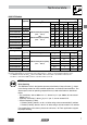
Technical data 480VAC Models Type Power [Hp/kW] Mains Output Current Voltage(1) Iin In 400V 480V 400V CLimmax(2) 480V 400V 480V Watts Loss ESV371N04TXB 0.5 / 0.37 1.7 1.5 1.3 1.1 175 200 23 ESV751N04TXB 1 / 0.75 2.9 2.5 2.4 2.1 175 200 37 ESV112N04TXB 1.5 / 1.1 ESV152N04TXB 2 / 1.5 ESV222N04TXB 3 / 2.2 ESV402N04TXB 5 / 4.0 ESV552N04TXB ESV752N04TXB 400 V Three-phase (3/PE) (340 … 440 V) OR 4.2 3.6 3.5 3.0 175 200 48 4.7 4.1 4.0 3.5 175 200 57 6.1 5.
Installation 3 Installation 3.1 Dimensions and mounting s2 4 X #10 18 lb-in b b1 M5 (420XNm ) s1 s1 s2 a a1 c b2 V0102 a a1 b b1 b2 c s1 s2 in (mm) in (mm) in (mm) in (mm) in (mm) in (mm) in (mm) in (mm) Type m lb (kg) ESV251…XB ESV371…XB ESV751…XB 3.90 (99) 3.10 (79) 7.50 (190) 7.00 (178) 0.25 (6) 4.35 (110) 0.6 (15) 2.0 (50) 2.0 (0.9) ESV112…XB ESV152…XB ESV222…XB 3.90 (99) 3.10 (79) 7.50 (190) 7.00 (178) 0.25 (6) 5.45 (138) 0.6 (15) 2.0 (50) 2.8 (1.3) ESV402…XB 3.
Installation 3.2 Electrical installation 3.2.1 Power Connections DANGER! Hazard of electrical shock! Circuit potentials are up to 600 VAC above earth ground. Capacitors retain charge after power is removed. Disconnect power and wait at least three minutes before servicing the drive. STOP! • Verify mains voltage before connecting to drive. • Do not connect mains power to the output terminals (U,V,W)! Severe damage to the drive will result. • Do not cycle mains power more than once every two minutes.
Installation 3.2.1.3 Mains connection to Three-Phase Supply ESV…N02Y… ESV…N02T… ESV…N04T… ESV…N06T… (3/PE AC) PE L1 L2 L3 PE 3.2.1.4 L1 L2 L3 Motor Connection U/T1 V/T2 W/T3 PE PES PES PE PES PES PES M 3~ PES = Protective Earth Shielding PE Mains and Motor Terminations 12 lb-in (1.3 Nm) 0.25 in (6mm) WARNING! Leakage current may exceed 3.5 mA AC. Minimum size of the protective earth conductor shall comply with local safety regulations for high leakage current equipment.
Installation 3.2.2 Fuses/cable cross-sections Note Observe local regulations. Local codes may supersede these recommendations Recommendations Type Fuse Miniature Fuse (2) or circuit Breaker(3) breaker(1) (N. America) Input Power Wiring (L1, L2, L3, PE) [mm²] [AWG] ESV251N01SXB M10 A C10 A 10 A 1.5 14 ESV371N01SXB M16 A C16 A 15 A 2.5 14 (1/N/PE) ESV751N01SXB M25 A C25 A 25 A 4 10 ESV251N01SXB, ESV251N02SXB, ESV371N01SXB, ESV371N02YXB M10 A C10 A 10 A 1.
Installation 3.2.3 Control terminals Terminal Data for control connections 1 Digital Input: Start/Stop 2 Analog Common input resistance = 4.3kΩ 5 Analog Input: 0...10 VDC 6 Internal DC supply for speed pot +10 VDC, max. 10 mA 25 Analog Input: 4...20 mA input resistance: 250Ω input resistance: >50 kΩ 4 Digital Reference/Common +15 VDC / 0 VDC, depending on assertion level 11 Internal DC supply for external devices +12 VDC, max.
Commissioning 4 Commissioning 4.1 Local Keypad & Display AUTO FWD REV RUN STOP V0105 START BUTTON: In Local Mode (P100 = 0, 4), this button will start the drive. RUN STOP BUTTON: stops the drive, regardless of which mode the drive is in.
Commissioning 4.2 Drive Displays and Modes of Operation Speed Mode Display In the standard mode of operation, the drive frequency output is set directly by the selected reference (keypad, analog reference, etc.). In this mode, the drive display will show the drive’s output frequency. PID Mode Display When the PID mode is enabled and active, the normal run display shows the actual PID setpoint. When PID mode is not active, the display returns to showing the drive’s output frequency.
Commissioning 4.5 Parameter menu 4.5.1 Basic Setup Parameters Code No. Possible Settings Name Start Control Source IMPORTANT Default Selection 0 0 Local Keypad Use RUN button on front of drive to start 1 Terminal Strip Use start/stop circuit wired into the terminal strip. See Section 3.2.
Commissioning Code No. Possible Settings Name IMPORTANT Default Selection Minimum Frequency 0.0 Maximum Frequency 60.0 0.0 {Hz} P103 7.5 {Hz} 500 • P102, P103 are active for all speed references • When using an analog speed reference, also see P160, P161 Note • P103 cannot be set below Minimum Frequency (P102) • To set P103 above 120 Hz: - Scroll up to 120 Hz; display shows (flashing).
Commissioning Code No. Possible Settings Name Start Method IMPORTANT Default Selection 0 0 Normal 1 Start on Power-up Drive will automatically start when power is applied. 2 Start with DC Brake When start command is applied, drive will apply DC braking according to P174, P175 prior to starting the motor 3 Auto Restart Drive will automatically restart after faults, or when power is applied.
Commissioning 4.5.2 I/O Setup Parameters Code No. Possible Settings Name Assertion Level IMPORTANT Default Selection 2 P120 and the Assertion Level switch must both match the desired assertion level unless P100, P121…P123 are all set to 0. Otherwise an F.AL fault will occur. 1 Low 2 High TB-13A Input Function TB-13B Input Function TB-13C Input Function 0 0 None Disables input 1 AUTO Reference: 0-10 VDC For frequency mode, see P160...
Commissioning Code No. Possible Settings Name IMPORTANT Default Selection Note • When input is activated, settings 1...7 override P101 • When TB-13A...TB-13C are configured for Auto References other than MOP, TB-13C overrides TB-13B, and TB-13B overrides TB-13A. Any other Auto Reference will have priority over MOP. • Settings 10...
Commissioning Code No. Possible Settings Name Relay Output TB-16, 17 IMPORTANT Default Selection 0 0 None Disables the output 1 Run Energizes when the drive is running 2 Reverse Energizes when reverse rotation is active 3 Fault De-energizes when the drive trips, or power is removed 4 Inverse Fault Energizes when the drive trips 5 Fault Lockout P110 = 3...
Commissioning Code No. Possible Settings Name TB-14 Output IMPORTANT Default Selection 0 Loss of Load Threshold 0 Loss of Load Delay 0.0 TB-30 Output 0 0...23 (same as P140) 24 Dynamic Braking For use with Dynamic Braking option 25 Network Activated Requires optional communication module (refer to the network module documentation). 0 {%} 200 0.0 {s} 240.
Commissioning 4.5.3 Advanced Setup Parameters Code No. Possible Settings Name IMPORTANT Default Selection Speed at Minimum Signal 0.0 -999.0 {Hz} 1000 Speed at Maximum Signal 60.0 -999.0 {Hz} 1000 f P161 0V (4mA) 10V (20mA) ref P160 V0111 Note • P160 sets the output frequency at 0% analog input • P161 sets the output frequency at 100% analog input • P160 or P161 < 0.
Commissioning Code No. Possible Settings Name (1) IMPORTANT Default Selection Slip Compensation 0.0 0.0 {%} 10.0 Current Limit 200 30 {%} DC Brake Voltage 0.0 0.0 {%} 30.0 DC Brake Time 0.0 0.0 {s} Increase P170 until the motor speed no longer changes between no load and full load conditions. CLimmax • When the limit is reached, the drive displays , and either the acceleration time increases or the output frequency decreases.
Commissioning Code No. Possible Settings Name Password 225 Clear Fault History 0 Program Selection IMPORTANT Default Selection 0000 9999 • Must enter password to access parameters • P194 = 0000: Disables password 0 No Action 1 Clear Fault History 0 Operate from User settings 1 Operate from OEM settings See Notes 1, 2 and 3 2 Reset to OEM default settings See Note 1 3 Reset to 60 Hz default settings • See Note 4 • Parameters are reset to the defaults listed in this manual.
Commissioning 4.5.4 PID Parameters Code No. Possible Settings Name PID Mode IMPORTANT Default Selection 0 0 Disabled • Normal-acting: As feedback increases, motor speed decreases • Reverse-acting: As feedback increases, motor speed increases • PID mode is disabled in Vector Torque mode (P300 = 5) 1 Normal-acting 2 Reverse-acting Note To activate PID mode, one of the TB-13 inputs (P121...P123) must be used to select the Auto Reference that matches the desired PID setpoint reference.
Commissioning Code No. Possible Settings Name IMPORTANT Default Selection Minimum Alarm 0.0 P204 P205 Maximum Alarm 0.0 P204 P205 Preset PID Setpoint #1 0.0 P204 P205 TB-13A activated; P121 = 3 and P200 = 1 or 2 Preset PID Setpoint #2 0.0 P204 P205 TB-13B activated; P122 = 3 and P200 = 1 or 2 Preset PID Setpoint #3 0.0 P204 P205 TB-13C activated; P123 = 3 and P200 = 1 or 2 Sleep Threshold 0.0 0.0 {Hz} 500.0 Sleep Delay 30.0 0.0 {s} 300.0 Sleep Bandwidth 0.
Commissioning 4.5.5 Vector Parameters Code No.
Commissioning Code No. Possible Settings Name IMPORTANT Default Selection (1) Motor Stator Resistance 0.00 0.00 {W} 64.00 (1) Motor Stator Inductance 0.0 0.0 {mH} 2000 Torque Limit 100 0 {%} 400 When P300 = 5, sets the maximum output torque.
Commissioning 4.5.6 Network Parameters Code No. Possible Settings Name IMPORTANT Default Selection Network Protocol 0 Not Active 1 Remote Keypad 2 Modbus RTU This parameter will only display the selection for the module that is installed. 3 CANopen 4 DeviceNet 5 Ethernet 6 Profibus Module Specific Parameters … 4.5.7 Diagnostic Parameters Code No. Refer to the Reference Guide specific to the module installed.
Commissioning Code No. Display Range (READ ONLY) Name IMPORTANT Analog Output 0 {VDC} 10.0 Actual Output Frequency 0 {Hz} 500.0 See P150…P155 Network Speed Command 0 {Hz} 500.0 Command speed if (Auto: Network) is selected as the speed source Terminal and Protection Status Indicates terminal status using segments of the LED display. (See section 4.5.7.1) Keypad Status Indicates keypad button status using segments of the LED display. (See section 4.5.7.
Troubleshooting and Diagnostics 5 Troubleshooting and Diagnostics 5.1 Status/Warning Messages Status / Warning Cause Remedy DC-injection brake active DC-injection brake activated Deactivate DC-injection brake • activation of digital input • deactivate digital input (P121...P123 = 18) • automatically (P110 = 2, 4...6) • automatically after P175 time • automatically (P111 = 1, 3) has expired Drive ID warning The Drive ID (P502) stored on the EPM does not match the drive model.
Troubleshooting and Diagnostics Status / Warning 5.2 Cause Remedy PID Mode Active Drive has been put into PID Mode. See P200. Sleep Mode is active See P240...P242 Start Pending The drive has tripped into a fault To disable Auto-Restart, set and will automatically restart P110 = 0...2 (P110 = 3...6) PID Mode disabled. Drive has been taken out of PID Mode. See P200.
Troubleshooting and Diagnostics 5.3 Fault Messages The messages below show how they will appear on the display when the drive trips. When looking at the Fault History (P500), the . will not appear in the fault message.
Troubleshooting and Diagnostics Fault Digital Input Configuration fault (P121...
Troubleshooting and Diagnostics Fault Cause Remedy (1) Motor Overload fault Excessive motor load for too long • Verify proper setting of P108 • Verify drive and motor are proper size for application Flying Restart fault Controller was unable to synchronize with the motor during restart attempt; (P110 = 5 or 6) Check motor / load Single-Phase fault A mains phase has been lost Check mains voltage Start fault Start command was present when • Must wait at least 2 seconds power was applied (P110 =
Notes
AC Technology Corporation • 630 Douglas Street • Uxbridge, MA 01569 • USA +1 (508) 278-9100 (SV01B)