
Installation Guide

15, 20 and 30 Amp Straight Blade or Locking Inlets
1. CABLE: Provide a cable of applicable ampacity, service and temperature ra�ng suitable
for the condi�ons of use and loca�on. The plugs and connectors are designed for use with
3, 4, or 5 conductor cables with a diameter from .375’’ to 1.156’’ (12/3 SJ through 8/5 S).
2. CORD CLAMP PREP: Gray colored cord clamp inserts preinstalled for use with .550’’ to .875’’
cable diameter. For other sizes:
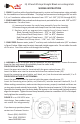
3. CABLE PREP: Remove outer jacket 2’’ and strip each individual conductor 5/8’’ as shown
in Figure 1 below. Make sure the wire is clean and a bright copper color. Do not solder the ends
of the wire. Feed the cable end through the housing.
When making connec�ons, make certain they are secure, properly insulated and there are
no stray wire strands outside the terminals. Tighten the terminal screws to 12-16 in-lbs torque.
Assemble the housing over the device body; the keyway in the housing and the body properly
aligns the two parts. Tighten the cord clamp assembly screws to a maximum 10-12 in-lbs torque.
Lastly �ghten the assembly screws.
FIGURE 2 is an L14-30P 4-wire
inlet design. Your product may
not match this image exactly.
If you have any ques�ons please
contact our Customer Service.
Direct: (414) 434-2220
Text: (414) 323-3240
www.ACWORKS.com
4. ASSEMBLY: Select the proper plug or connector for your applica�on. Loosen the screws
from the face and remove the assembly from the outer body.
FOR DEVICES WITH A W TERMINAL:
Insert the green wire into the terminal with the green colored screw. (G)
Insert the white wire into the terminal with the silver colored screw. (W)
Insert the reamaining wires (white, red, black, etc.) into the terminals marked X, Y or Z.
FOR DEVICES WITHOUT A W TERMINAL:
Insert the green wire into the terminal with the green colored screw. (G)
Insert the remaining wires (white, red, black etc.) into the terminals marked X, Y or Z.
A. Loosen and remove the cord clamp assembly from the housing.
B. Remove the gray colored cord clamps from the cord clamp assembly.
C. Replace with an appropriate supplied cord clamp insert:
Black Colored Cord Clamp Insert - .375’’ to .550’’ diameter
Gray Colored Cord Clamp Insert - .550’’ to .875’’ diameter
Red Colored Cord Clamp Insert - .750’’ to 1.06’’ diameter
Without Cord Clamp Insert - 1.06’’ to 1..156’’ diameter
WIRING INSTRUCTION
Green (G)
Black (Y or X)
White (W)
Red (X or Y)
FIGURE 1