Main Menu Table of Contents Preparation of Work Description • Most monocoque bodies are composed as a single unit by welding together pressed parts made of steel plates which come in a variety of different shapes and sizes. Each part is responsible for displaying a certain strength and durability in order that it may play its role in meeting the functions of the body as a whole.
Main Menu Table of Contents Checkpoints • Accurate Inspection of Damaged Parts (Visual) Seat Belts Replace the seat belts if: 1. The belt material is cut, punctured, burned or in any way damaged. 2. The buckle or retractor does not work properly. 3. They were being worn at the time of a collision (check for damage at the seat belt anchor points). 4. Their condition is questionable. Front Section: 1. Is there any bending, splitting, denting or other damage to the suspension and its related parts? 2.
Main Menu Table of Contents Preparation of Work Correction of the Damaged Area Set the frame corrector on the car body. The side sill is flangeless to allow reshaping by pulling it out. Use the horizontal pinch welds for anchoring the car.
Main Menu Table of Contents 1. Apply load to the damaged section and pull it out until the section is almost restored to the original shape. 2. Check that the parts of the body they cover have been more or less restored to their original shapes. NOTE: Check the original position using the body dimensional drawings (see section 6) and the positioning jigs (see page 1-7). 3. Remove the parts that require replacement. 4.
Main Menu Table of Contents Preparation of Work Measurement (Excluding small damage) Whenever possible, make judgements and conclusions based on measurement. Measure the wheel alignment (see page 1-2) so as to prevent any future trouble like unsymmetrical wear of the tires or catching of the steering wheel. If there are any deviations, use a tram tracking gauge and measure parts of the body. POINTER A If there is any twisting to the body, measure using a frame centering gauge.
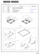
Main Menu Table of Contents Positioning Jigs 4-12, 4-18, 4-50, 4-55 4-12, 4-18 4-50, 4-55
Main Menu Table of Contents Welding Methods/Repair Tools Spot Welding Spot welding is also known as resistance spot welding, and it is the most suitable method of welding for automobiles. It has three main features: the welding can be performed instantaneously, it exercises very little effect on the mother material, and it reduces the generation of distortion to the absolute minimum.
Main Menu Table of Contents • Welding Strength Test Even if you perform the welding in accordance with the conditions, the strength of the welded sections may fluctuate widely with drops in the voltage and other factors. The quality of the welding cannot be evaluated unless the welded sections are destroyed. Provide yourself with a steel plate of the same thickness and conduct a destruction test. • If holes appear in the steel plates, this means that the welding is standard strength.
Main Menu Table of Contents Welding Methods/Repair Tools Gas Welding Gas welding is indispensable for body repair because of the broad range of its applications for joining the body panels, cutting the materials that construct the body, and applying heat to reform panels, and also because it is easy to get hold of the tools. However, this method requires experience.
Main Menu Table of Contents Carbon Dioxide Arc Welder (MIG Arc Weld) This welding process uses inexpensive carbon dioxide instead of expensive inert gases as a shielding means. Consumable metal electrodes are employed. It has a wide range of applications, including butt welding of thin plate, fillet welding, plug welding, and MIG spot welding. In terms of the weld strength, it is also highly stable. Welders: CAUTION: Disconnect the negative battery cable before arc welding.
Main Menu Table of Contents Welding Methods/Repair Tools Examples of Repair Tools Item Protective tools Work Operator Tools, equipment used 1. 2. 3. 4. 5. 6. Protective goggles Cap Ear plug Shield for eyes Overalls with long sleeves Dust-proof mask 7. Protective apron 8. Welding gloves 9. Foot protectors 10. Safety shoes 11. Work gloves 12. Spattering guard Heat-resistant protective cover.
Main Menu Table of Contents Item Tools, equipment used Work Flange tools Edge preparation Cutting tools Cutting AIRSAW AIR IMPACT CUTTER AIR JIGSAW HANDSAW HAND NIBBLER CHISEL PLASMA CUTTER Sanding tools Cleaning DISC SANDER Air type: BELT SANDER Electric type:
Main Menu Table of Contents Welding Methods/Repair Tools Examples of Repair Tools (cont'd) Item Fixing tools Work Tools, equipment used Base metal fixing SCREW CLAMP VISE-GRIPS SQUILL VISES Shaping tools Skin panel shaping HAMMERS DOLLIES CHISEL SNIPS/ SHEARS SPOONS Body, frame shaping WELDER BODY JACK SLIDE HAMMER
Main Menu Table of Contents General Information Zinc-plated Steel Plate Repair The zinc-plated steel plate used in some panels of the Acura 2.5TL/3.2TL requires different repair techniques than ordinary steel plate. Refer to "Body Construction" (see page 4-2) for the location of the zinc-plated panels. ZINC PLATING (5~6 microns) Steel plate 1. Before spot welding the zinc-plated steel plate, remove the paint from both sides of the flange to be welded. Apply sealer to the flange after welding.
Main Menu Table of Contents Avoid puttying as much as possible when repairing a new car. Use alternative methods as much as possible. • Most paints contain substances that are harmful if inhaled or swallowed. Read the paint label before opening the container. Spray paint only in a well ventilated area. • Cover spilled paint with sand, or wipe it up at once. • Wear an approved respirator, gloves, eye protection and appropriate clothing when painting. Avoid contact with skin.
Table of Contents Main Menu General Information Door and Bumper Reinforcement Beams Door and bumper reinforcement beams used on Honda automobiles are made from a metal equivalent to High Strength Steel (except 2.5TLfront bumper reinforcement beam). Should High Strength Steel be heated, the strength of the steel will be reduced. If High Strength Steel is damaged, as in a automobile accident where the door reinforcement beams are bent, the beams may crack should any attempt be made to straighten them. 2.
Main Menu Table of Contents Construction NOTE: Be sure to use epoxy-based putty and primer surfacer to make any repairs on paint coats or zinc-plated sheet metal (see page 3-3).
Table of Contents Main Menu Front Fender Replacement NOTE: Check clearance and level differences of the hood, door panels and front bumper. 5. Set the front fender. Fasten to the front wheelhouse at two spots with bolts. Close the hood and check the front and rear clearances, 1. door clearance and level differences. Remove the related parts. • Front bumper • Headlight • Mud guard • Side sill panel • Inner fender 2. Mask parts with tape.
Main Menu Table of Contents Front Bulkhead Description The front bulkhead is joined to the front wheelhouse and front side frame. It forms the base for the headlights and other parts and maintains the rigidity of the front section of the body. Pay particular attention to twists and parallelism and check mounting of related parts when welding. Mass Production Body Welding Diagram 2.5TL: 3.
Main Menu Table of Contents Replacement 1. Remove the related parts. NOTE: When drilling holes be careful not to drill down • Front bumper to the front wheelhouse or front side frame themselves. • • Hood Right and left headlights • Cut off the bulkhead with an air chisel, leaving the • Right and left front fenders welding flanges intact. • Level and finish the burrs from the pried off spot • Radiator, condenser • Hood latch welds with a disc sander.
Main Menu Table of Contents Front Bulkhead Replacement (cont'd) 5. 7. Mold the damaged related parts. • Use a hammer and dolly to mold the damaged areas To prevent eye injury and burns of the front wheelhouse front and side frame. when welding, wear an approved welding helmet, • Even out the welding flanges with a hammer and dolly. • gloves and safety shoes. Spot weld the clamped sections. Fill all drilled holes by MIG or gas welding.
Main Menu Table of Contents 10. Perform the main welding. 3.2TL: • Spot weld the bulkhead as shown. • Make 20% to 30% more spot welds than there were holes drilled. To prevent eye injury and burns when welding, wear an approved welding helmet, gloves and safety shoes. 2.5TL: 12. Apply the undercoat (see section 7). 13. Attach the front fender. 3.2TL 14. Lower the body. NOTE: Tighten the wheel nuts to the specified torque. Torque: 108 N-m (11.0 kgf-m, 79.6 Ibf-ft) 15. Apply the paint.
Main Menu Table of Contents Front Wheelhouse/Damper Housing Description The front wheelhouse component is constructed as a unit with the front damper housing. Therefore, replacement of the component affects the front wheel alignment. When assembling it, either use a positioning jig or follow dimensions on the frame repair chart for positioning. Weld carefully.
Main Menu Table of Contents Front Wheelhouse/Damper Housing Mass Production Body Welding Diagram 2.
Main Menu 3.
Main Menu Table of Contents Front Wheelhouse/Damper Housing Replacement 1. Remove the related parts. • Parts to be removed when removing the front bulkhead • Parts on passenger side of lower dashboard which are especially flammable • Electrical accessories in engine compartment and wire harnesses. NOTE: See the 95-96 Acura 2.5TL & 96 Acura 3.2TL 4. Cut and pry off the front wheelhouse and damper housing. -1. When replacing the front wheelhouse only.
Main Menu Table of Contents -2. Replace the damper housing with the front 2.5TL: wheelhouse. • DASHBOARD UPPER SIDE MEMBER Remove the wheelhouse upper rear member. • Remove the MIG weld flange with a disc sander. To prevent eye injury, wear goggles or safety glasses whenever sanding, cutting or grinding. • Using a chisel, pry off the welded flange form the front pillar and damper housing. NOTE: Remove the wheelhouse upper rear member carefully so they can be reused. 2.
Table of Contents Main Menu Front wheelhouse/Damper housing Replacement (cont'd) 5. Mold the related parts. • Level and finish the burrs left on the welding surfaces with a sander. • Ventilate when Use a hammer and dolly to even out the welded areas of paint. Most paint contains substances that are harmful if inhaled • Fill all drilled holes by MIG or gas welding. the lower dashboard, front side frame and dashboard spraying or swallowed.
Main Menu 8. Table of Contents Perform the main welding. • Weld as much as possible with the jig still mounted. To prevent eye injury and burns when welding, wear an approved welding helmet, gloves and safety shoes. • 9. Weld the wheelhouse upper rear member. When the upper rear member is to be reused, make MIG welds at the drilled holes. 3.2TL: 2.5TL: Make 20% to 30% more spot welds than there were holes drilled. 2.5TL: 10. Finish the welded area.
Main Menu Table of Contents Front Side Frame Description The front side frame acts as a base for the front suspension and is highly important in maintaining the rigidity of the front section. Pay careful attention to the position and dimensions of the weld joints and weld carefully.
Main Menu Table of Contents Front Side Frame Mass Production Body Welding Diagram 2.5TL: NOTE: Replace the front side frame and front side outrigger as an assembly.
Main Menu Table of Contents 3.2TL: NOTE: Replace the front side frame and front side extension as an assembly.
Main Menu Table of Contents Front Side Frame Replacement NOTE: With the front bulkhead removed. 1. Remove the related parts. • Front suspension related parts • Brake hoses and pipes • • Engine compartment electrical components Fittings in passenger compartment, etc. 3. Roughly pull out and straighten the damaged area. • Attach the car to the frame straightener by tightening the underbody clamps located at the horizontal • Steering gearbox. 2. pinch welds. NOTE: Refer to the 95-96 Acura 2.
Table of Contents Main Menu Remove the burrs from the drilled sections with a disc sander. To prevent eye injury, wear goggles or safety glasses whenever sanding, cutting or grinding. NOTE: When drilling holes and be careful not to drill down to the inside sill. 2.5TL: • Center punch around the spot weld imprints on the front side frame and front side outrigger from inside the passenger compartment. • Drill holes in the spot welded area with a 5 mm (0.2 in) drill.
Main Menu Table of Contents Front Side Frame Replacement (cont'd) 7. Set the new front side frame. • Remove the undercoat from the both sides of the welding section, and expose the steel plate using a disc sander. To prevent eye injury, wear goggles or safety glasses whenever sanding, cutting or grinding. NOTE: Apply the spot sealer to the welding surface when spot welding. • Tighten the front side frame against the front floor and side sill using vise-grips or pliers.
Main Menu 8. Table of Contents Perform the main welding. • Make 20% to 30% more spot welds than there were holes drilled. • Weld as much as possible with the jig still mounted. 3.2TL: To prevent eye injury and burns when welding, wear an approved welding helmet, gloves and safety shoes. • Weld the front side frame, wheelhouse, damper housing and bulkhead. • From the passenger compartment side, plug weld the holed areas of the lower dashboard and front floor with a MIG welder. 2.
Main Menu Table of Contents Front Side Frame Replacement (cont'd) 3.2TL: 12. Apply the undercoat. Undercoat the front floor, and apply anti-rust agent to the inside of the welding section of the side sill, front side frame, etc (see section 7). 13. Install the related parts. Install in the reverse order in which they were removed. 14. Inspect, check and adjust. • • • 9. Finish the welds.
Main Menu Table of Contents Front Side Outrigger/Front Side Extension Description The front side outriggers connect the front side frames to the body and are vital to the rigidity of the entire body frame. Pay particular attention when welding the front side outriggers from beneath the front floor and side sill.
Main Menu Table of Contents Front Side Outrigger/Front Side Extension Mass Production Body Welding Diagram 2.5TL: NOTE: Replace the front side outrigger, locating bracket and front side brace as an assembly.
Main Menu Table of Contents Front side Outrigger/Front Side Extension Mass Production Body Welding Diagram (cont'd) 3.
Main Menu Table of Contents Replacement 1. Remove the related parts. • Front seat • Carpet • Refer to the front side frame (see page 4-16). 2. Pull out and straighten the damaged area. • The front side outrigger receives impact through the front side frame or side sill. Such impact generally requires replacement of all these parts.
Main Menu Table of Contents Front Side Outrigger/Front Side Extension Replacement (cont'd) 3.2TL: 6. FRONT SIDE EXTENSION FRONT SIDE FRAME Set the new front side outrigger. • Remove the undercoat from both sides of the areas to be spot welded with a sander to expose the steel plate. • Clamp the weld flanges with the side sill using the vise-grip pliers. Set the front side outrigger on the side frame using a jack. • Drill 3 mm (0.
Main Menu Table of Contents Make 5 mm (0.2 in) holes in the MIG weld holes with the outrigger or front side extension, and weld the front side frame, floor frame and inside sill with a MIG welder. 8. Apply the sealer (see section 5). Apply sealer to the mating surface of the lower dashboard and front floor. 9. Apply the paint. See Paint Repair section. 2.5TL: 6 point of MIG welding the bending angle of a flange. Welding pitch=30 mm (1.2 in) • Ventilate when spraying paint.
Main Menu Table of Contents Front Pillar (Outer Panel) Description The front pillar is connected to the roof, windshield, the door hinges, and side sills and is a highly important support. Connection of the front pillar determines the position of the windshield and front door. Align the front fender, door, and windshield while the front pillar is loosely mounted, and check the clearances and level differences.
Main Menu Table of Contents Replacement 1. Remove the related parts: 4. Cut off the front pillar. • • Hood Front fender • Cut off the front pillar along the bold line shown in the figure to the right with a gas cutter. • Front door • Use a handsaw to cut the windshield and side sill • Windshield • Front side trim areas. NOTE: Be careful not to cut the inner section. • Door opening trim • Side cowl lining • Dashboard • • Front pillar trim • Drill holes using a spot cutter.
Table of Contents Main Menu Front Pillar (Outer Panel) Replacement (cont'd) 5. 8. Mold the related parts. • Remove the vise-grips, then mount the door. • Check the clearance and level differences of the Fill any holes by MIG or gas welding, and even out with a hammer and dolly. door and fender. To prevent eye injury and burns when welding, wear an approved welding helmet, gloves and safety shoes. 6. Set the repair part • Align the repair part with the top cut section, then cut it with a handsaw.
Main Menu Table of Contents 10. Finish the welding areas. • Finish grind the finishing allowance with a disc sander until it is smooth. To prevent eye injury, wear goggles or safety glasses whenever sanding, cutting or grinding. • Smooth the flanged section of the door opening with a hammer and dolly. 11. Apply the sealer (see section 5). 12. Apply the paint. See Paint Repair section. • Ventilate when spraying paint. Most paint contains substances that are harmful if inhaled or swallowed.
Main Menu Table of Contents Windshield Lower Description Impact damage to the windshield lower area may spread to the back of the panel and wiper mounting area, calling for replacement of the affected skins.
Main Menu Table of Contents Windshield Lower Replacement 1. Remove the related parts. Wiper arm and motor Windshield Right and left front fenders Right and left front door opening trims Front pillar trim Hood Dashboard, etc Wire harnesses and electrical accessories Steering column 2. Cut the windshield lower and separate the welded flange. • Center punch around the spot weld imprints. • Drill holes with a spot cutter through the nuggets. • Peel off the welding flange using a chisel.
Main Menu Table of Contents LOWER SUPPORT A/C DUCT SHELTER DASHBOARD UPPER SIDE BULKHEAD CENTER DEFROSTER DUCT DASHBOARD UPPER 3. Set the new windshield lower. • Apply an undercoat and body paint to the inside. • Ventilate when spraying paint. Most paint contains substances that are harmful if inhaled or swallowed. Read the paint label before opening the paint container. • Avoid contact with skin. Wear an approved respirator, gloves, eye protection and appropriate clothing when painting.
Main Menu Table of Contents Side Sill (Outer Panel) Description The side sill should, depending on the degree of damage, be repaired as much as possible rather than replaced. (Repair by pulling out with slide hammer with pin and washer welded on.
Main Menu Table of Contents Replacement • If the damage involves part of the center pillar and 1. Remove the related parts. rear wheel arch, cut them as shown with a handsaw. • Front and rear doors • Cut the side sill with a chisel leaving the weld flanges (remove according to part damaged) intact. • Side and center pillar trim 2. 3. • Door opening trim • Carpet • Door switch • Center punch around the spot weld imprints on the welded flange. • Drill holes using the spot cutter.
Table of Contents Main Menu Side Sill (Outer Panel) Replacement (cont'd) 2.5TL: WHEEL ARCH EXTENSION BULKHEAD NOTE: Check the damage of the honeycomb floors and if necessary replace it (see page 4-58). CENTER PILLAR STIFFENER INSIDE SILL CENTER INNER PILLAR HONEYCOMB FLOORS BULKHEAD REINFORCEMENT SIDE SILL EXTENSION 5. CENTER PILLAR STIFFENER Set the repair part. • Sand off the undercoat from both sides of the welded flange on the repair part. • Clamp the repair part in place with vise-grips.
Main Menu 7. Table of Contents Perform main welding. To prevent eye injury and burns when welding, wear an approved welding helmet, gloves and safety shoes. • Weld the side sill and rear side outer joints with a MIG welder. • Spot weld the side sill flanges. • Make 20% to 30% more spot welds than there were holes drilled. • Make 5 mm (0.2 in) holes in the MIG weld holes with the repair part, and weld the center pillar stiffener and wheel arch extension with a MIG welder.
Main Menu Table of Contents Roof Panel Description Deformation of the roof panel is highly noticeable in terms of the vehicle's outer appearance. Before replacing the roof rail, make sure that the body is horizontal. Before welding the roof panel, adjust the roof rail flanges so that they contact the roof panel.
Main Menu Table of Contents Replacement 1. Remove the related parts. 4. Windshield Rear window Sunvisor Ceiling lights Headliner Moonroof frame (For some types) 2. Cut off the shaded areas of the roof panel. • Cut the roof rail weld flange with a handsaw at the four corners. • Using a chisel, pry off the roof panel along the bold lines as shown. • Center punch around the spot weld imprints of the roof gutter welded flange.
Main Menu Table of Contents Roof Panel Replacement (cont'd) Level and finish burrs on the welded flanges with a disc sander. 14 mm (0.6 in) OUTER PANEL To prevent eye injury, wear goggles or safety glasses whenever sanding, cutting or grinding. ROOF PANEL • Even out the roof side rail welded flange with a hammer and dolly for a close fit with the roof panel welded flange. NEW ROOF PANEL ROOF SIDE RAIL REAR INNER PANEL 5. Apply paint to the underside of the new roof panel.
Table of Contents Main Menu • Smooth the spot weld areas under the windshield and rear window with a hammer and dolly. NOTE: After welding the pillars, grind and finish the welded areas flat and blend them into the roof panel. 9. Apply and level the sealer to the welded areas. 10. Apply the paint. See Paint Repair section. • Ventilate when spraying paint. Most paint contains substances that are harmful if inhaled or swallowed. Read the paint label before opening the paint container.
Main Menu Table of Contents Rear Side Outer Panel Description The rear side outer panel is a conspicuous part of the vehicle. It is especially important for body line continuing from the door. Therefore, pay particular attention to it when conducting work. This part also is next to the trunk lid, door and rear window and other parts and must be aligned with them.
Main Menu Table of Contents Replacement 1. Remove the related parts. • • • • • • • • Rear bumper Rear window Taillight Rear pillar trim panel Trunk side panel Rear seat Rear seat belt Fuel fill pipe (left side only) Do not smoke while working near the fuel system. Keep open flame away from the fuel system. If necessary, remove the fuel tank and/or lines before welding nearby. Drain fuel into an approved container. PLASTIC GROMMET MOUNTING HOLE Do not smoke while working near the fuel system.
Table of Contents Main Menu Rear Side Outer Panel Replacement (cont'd) REAR DAMPER SEPARATOR OUTER PANEL REAR DAMPER STIFFENER Apply the mastic sealer. REAR PANEL REAR PARCEL SHELF TRUNK GUTTER INNER PANEL REAR PANEL WHEEL ARCH EXTENSION REAR FLOOR SIDE SILL EXTENSION 5. Cut the replacement part. • Cut so that the repair part overlaps the side sill by 30 mm (1.2 in). • Apply body paint to the back of the repair part. • See Paint Repair section. 4. Mold the inner panel and related parts.
Table of Contents Main Menu 9. Perform the main welding. To prevent eye injury and burns when welding, wear an approved welding helmet, gloves and safety shoes. • Weld the outer panel at the rear pillar and side sill with a MIG welder. • Make 20% to 30% more spot welds than there were holes drilled. • Make 5 mm (0.2 in) hole in the MIG weld hole with the repair part, and the wheel arch extension with a MIG welder. REPAIR PART 6. Set the repair part.
Table of Contents Main Menu Rear Side Outer Panel Replacement (cont'd) 13. Apply the undercoat. Apply undercoat to the wheelhouse and apply anti-rust agent to the inside of the outer panel (see section 7). 14. Install the related parts. Install in the reverse order in which they were removed. 15. Inspect, check, and clean. • Adjust the clearance with the door and trunk lid, then adjust the level differences and fit. Check operation. • Test for leaks in the trunk and passenger compartments.
Main Menu Table of Contents Rear Panel Description The rear panel is joined to the rear outer panel and rear floor, and maintains the rigidity of both sides of the rear body. It must be welded carefully.
Table of Contents Main Menu Rear Panel Replacement 1. 4. Mold the related parts. Remove the related parts. • Rear bumper • Repair the rear floor upper stiffener if necessary. • Rear bumper upper beam • Trunk lid lock and its attachments • Repair all cracks, holes or other defects by MIG or gas welding. • Other related parts • Rear and side trim panels • Taillights 2. To prevent eye injury and burns when welding, wear an approved welding helmet, Pull out and straighten the damaged area.
Main Menu Table of Contents 5. Set the new rear panel. • Paint the inside of the panel with the body color. • See Paint Repair section. 6. Tack weld the rear panel. • Weld the clamped sections for temporary installation. To prevent eye injury and burns when welding, wear an approved welding helmet, gloves and safety shoes. • Ventilate when spraying paint. Most paint contains substances that are harmful if inhaled or swallowed. Read the paint label before opening the paint container.
Main Menu Table of Contents Rear Panel Replacement (cont'd) 9. Finish the welding areas. • Level the welded acres with a disc sander, then even out high areas with a hammer. Be careful not to deform them. To prevent eye injury, wear goggles or safety glasses whenever sanding, cutting or grinding. • Even out the spot welded flange area with a hammer and dolly. 10. Apply the sealer (see section 5). • Apply sealer to the rear side outer joint and around the taillight areas of the rear panel.
Main Menu Table of Contents Rear Floor Description The rear floor is the base of the rear body and it is critical for the rigidity of the rear body. During replacement, refer to the body dimension chart or body correction chart and determine the position to set the rear floor properly. Be sure that the rear floor is not bent or deformed. Weld securely following the welder manufacturer's instructions to maintain the rigidity of the body.
Main Menu Table of Contents Rear Floor Replacement 1. Remove the related parts. • 3. Remove the rear floor upper extensions. Rear seat • Trim and other luggage compartment fittings • Left and right rear suspension assembly • Parking brake parts • Muffler • Wire harness • Other parts as necessary • Fuel tank and fuel pipes Do not smoke while working near the fuel system. Keep open flame away from the fuel system. If necessary, remove the fuel tank and/or lines before welding nearby.
Table of Contents Main Menu 7. • Cut and pry off the rear floor. • Cut off the rear floor with a gas cutter or air chisel. Level the spot welded flanges of the rear side frame and rear floor cross member, as shown by the bold line in the figure below. Center punch around the spot weld imprints on the remaining welded flanges. Do the same with the rear wheelhouse and the side of the rear end inner panel. • Drill holes with a spot cutter.
Table of Contents Main Menu Rear Floor Replacement (cont'd) • Smooth the welding flanges of the rear frame with a hammer and dolly. • Pry off the welded flange sections using a chisel. REAR FLOOR UPPER CROSS MEMBER NOTE: Check that the rear frame is parallel at the right and left. REAR FLOOR UPPER CROSS MEMBER REAR FLOOR 9. Keep the body level. Jack-up the body at the front and back. Place safety stands at the four designated places of the side sill. REAR FRAME REAR FLOOR CROSS MEMBER 10.
Main Menu Table of Contents • Insert the repair part between the rear floor and rear floor upper cross member. • Check that the weld flange surfaces fit closely. 11. Set the rear floor upper stiffener, and check the rear panel position. REAR FLOOR UPPER STIFFENER 12. Perform the main welding. To prevent eye injury and burns when welding, wear an approved welding helmet, REAR FLOOR UPPER CROSS MEMBER REPAIR PART gloves and safety shoes.
Table of Contents Main Menu Rear Floor Replacement (cont'd) • Make 5 mm (0.2 in) hole in the MIG weld hole with the repair part. • Weld the rear floor, repair part and rear floor upper cross member. • Weld the rear panel and install the rear floor upper extension. 13. Finish the welded area. Even out the welded area with a hammer and dolly, and fit the flange surfaces closely together. 14. Apply the sealer.
Main Menu Table of Contents Rear Floor Cross Member Description The rear floor cross member position is critical for rear wheel alignment. During replacement, check the position of the rear beam and rear damper base and position the rear floor cross member properly. Weld securely following the welder manufacturer's instructions to maintain rigidity. Use of the positioning jig is recommended.
Main Menu Table of Contents Rear Floor Cross Member Replacement 1. See Rear Floor Replacement for removal of related • Center punch around the spot weld imprints on the rear frame. parts. 2. • Drill holes with a spot cutter. • Be careful not to let them penetrate through to the Peel off the undercoat. Heat the undercoat at the weld areas of the rear floor rear frame. and rear frame with a gas torch, and peel off the • Pry off the part with a chisel. undercoat with a metal spatula.
Main Menu Table of Contents 6. Finish the welding area. Roughly grind the welds in the trunk compartment with a disc grinder. Be sure to leave the finishing allowance. NOTE: Take care not to grind excessively. 7. Apply the sealer (see section 5). 8. Apply the paint. See Paint Repair section. • Ventilate when spraying paint. Most paint contains substances that are harmful if inhaled or swallowed. Read the paint label before opening the paint container. • Avoid contact with skin.
Main Menu Table of Contents Honeycomb Floors (2.5TL) NOTE: What is known as "honeycomb" construction is employed for the front floor. Properly designed and applied, it plays an important role in maintaining the structural rigidity of that section of the car's floor. The honeycomb floor is installed with an epoxy resin adhesive. Care must be exercised when installing a new honeycomb floor as seepage of water into the honeycomb construction will adversely affect its performance. Replacement 3.
Main Menu Table of Contents 4. Application of adhesive. • Apply adhesive all over the melt-sheet. 6. Application of dust sealant. • Apply dust sealer all the way around the floors. NOTE: Use CEMEDINE EP-330 or equivalent (epoxy resin adhesive designed to harden quickly at normal temperature). Follow the adhesive manufacturer's instructions. NOTE: It is essential to make the floor completely impervious to water as seepage into honeycomb construction will adversely affect its performance.
Main Menu Table of Contents Cross Section of Body and Sealants NOTE: Seal the following areas to prevent air leaks, water leaks and rust. : Sealing locations Spot Sealer: 3M #08892 (Internal) : 3M #08893 (External) Use materials above or equivalents. 2.
Main Menu Table of Contents
Main Menu Table of Contents Cross Section of Body and Sealants (cont'd) 2.
Main Menu Table of Contents
Main Menu Table of Contents Cross Section of Body and Sealants (cont'd) 2.
Main Menu Table of Contents 3.2TL: < Engine Compartment > NOTE: The sealing locations of except those above are the same as 2.5TL.
Main Menu Table of Contents Cross Section of Body and Sealants Spot/Mastic Sealers NOTE: Seal the following areas to prevent air leaks, water leaks and rust.
Main Menu Table of Contents Body Dimensional Drawings Upper Body Measuring Dimensions 2.5TL: Unit: mm (in) NOTE: Measuring dimensions show the distance between the forward or upper edge of positioning bosses and/or holes shown in the detail sketches.
Main Menu 3.
Main Menu Table of Contents Body Dimensional Drawings Upper Body Measuring Dimensions (cont'd) Unit: mm (in)
Main Menu Table of Contents Under Body Measuring Dimensions 2.
Main Menu Table of Contents Body Dimensional Drawings Under Body Measuring Dimensions (cont'd) 3.
Main Menu Opening Repair Chart Unit: mm (in) Table of Contents
Main Menu Table of Contents Body Dimensional Drawings Frame Repair Chart 2.
Main Menu Table of Contents
Main Menu Table of Contents Body Dimensional Drawings Frame Repair chart NOTE: The dimensions of the rear floor area are the same as the table on page 6-9. 3.
Main Menu Table of Contents Rust-preventive Treatments General Corrosion starts immediately after the steel base contacts the atmosphere. The condition is aggravated by sea wind, road salt, rain, snow and industrial fallout. There are many ways to protect automobiles against corrosion. Primers, primer surfacers and paints are applied by electrodeposition or spray to protect the car body. Anti-rust Agents and Spray Guns Use the following anti-rust agents or equivalents when making a body repair.
Main Menu Table of Contents Diagram NOTE: • Apply the designated thickness over surfaces including gaps and edges. • Avoid spraying agents on following parts: Window glass, lights, grille, exhaust parts, tires, bumper and lower skirt. • Wipe up spilled agents at once from rubber and plastic parts. Anti-rust Agents: • Use RUSTOP, DEOX #100, WAXOYL or equivalents for protecting inner surfaces. • Use NOX-RUST 409-20S, SOLTON 1000S or equivalents for protecting outer surfaces.
Main Menu Table of Contents Rust-preventive Treatments Areas to be Covered by Anti-rust Agents Rust-preventive Treatments: Front Bulkhead Area • With the hood opened, coat the joints of the bulkhead, wheelhouse and side frame and around the back of the headlight assembly. Nozzle used: B Hood, Underside • Coat the entire panel and seams all the way around. • Spray sufficient anti-rust agent to the front area and each corner. • Apply rust-preventive agent or grease to the hood hinges.
Main Menu Table of Contents Front Fender, Underside Outside Panel (Front Pillar and Center Pillar), Inside Apply anti-rust agent to the end of the fender, wheelhouse, • Remove the door harness grommet and insert the nozzle facing down. and side sill installation. NOTE: NOTE: Make sure that the nozzle is not interfering with the door hinge bracket. Spray thoroughly. • Apply a coat of agent to the front door side, wheel arch • Coat the door checker bracket. end.
Main Menu Table of Contents Rust-preventive Treatments Areas to be Covered by Anti-rust Agents (cont'd) Doors, Inside • Apply agent to the joint between the door stiffener and door skin through the water drain hole at the bottom of the door. • If necessary, remove the door side molding and weatherstrip, then spray the agent through the hole. NOTE: When a suction type spray gun is used, remove the door trim panel.
Main Menu Table of Contents Trunk Lid Inside • Coat the trunk lid skin, and frame seams all the way around. • On the trunk lid, apply the agent to the inside of the reinforcement frame. Nozzle used : B Nozzles used: A and B Front Side Frame, Inside • Remove the grommets from inside the front compartment and coat the inside of the front side frame. • Coat the battery mount bracket base.
Main Menu Table of Contents Rust-preventive Treatments Areas to be Covered by Anti-rust Agents (cont'd) Front Wheelhouse • Spray agent on the wheelhouse, front fender stay, upper member and damper bracket as shown. • Undercoat the wheelhouse where anti-rust agent or undercoat has not yet been applied. NOTE: • Coat the wheelhouse extension, particularly the upper face.
Main Menu Table of Contents Under-Floor • • Apply the agent to the shaded areas only. Do not apply it to the exhaust system and heated oxygen sensors. Coat the bottom of the fuel tank. Nozzle used: C Suspension NOTE:Do not apply to the brake disc and brake caliper.
Main Menu Table of Contents Rust-preventive Treatments Undercoating Diagram indicates PVC coating areas. NOTE: • Coating thickness: 0.5 mm (0.02 in) MIN. • Follow the above instructions for paint repair or refinishing. • Avoid coating on the front and rear suspensions, and exhaust system mount area. • Items marked with an asterisk (*) on the important control areas. Coating thickness 1 mm (0.04 in).
Main Menu Table of Contents Color Chart Painting Specifications NOTE: • Apply NH-86 black (Gloss 40) to the visible surfaces of shadowed areas after installing equipment (except cars painted with NH-503P). • In case of NH-503P there is no need to paint black. • With body colors are NH-585P, NH-578, YR-509P. G-79P, R91P and YR-506M, apply NH-86 black (Gloss 40) to the front and rear wheelhouses.
Main Menu Table of Contents Paint General The 3-coat•3-bake (3C•3B) and 4-coat•4-bake (4C•4B) paint finishes give the Acura 2.5TL/3.2TL a deep gloss and stunning finish. This manual provides information on paint defect repair and refinishing. Throughout, the objective is to explain in a simple yet comprehensive manner the basic items you should know about paint repairs. Select the correct material for the defect and repaint or refinish in the correct manner as described in this manual.
Main Menu Table of Contents Paint Intermediate Coat Colors The intermediate coat will determine the color and quality of the paint finish (smoothness, gloss, brightness and thickness). Be sure to follow mixing instructions explicitly and measure the paint accurately.
Table of Contents Main Menu Paint Refinishing Paint damage can appear in any form. Before making a repair, check the damaged area carefully, and determine the procedure best suited to the type. The following relates paint refinishing methods to various types of paint damage of damage or defects. Defects and Refinishing Processes • Ventilate when spraying paint. Most paint contains substances that are harmful if inhaled or swallowed. Read the paint label before opening the paint container.
Main Menu Paint Refinishing Processes Table of Contents
Table of Contents Main Menu Refinishing Procedures 1. Featheredging (polishing damaged areas) • Do not use high air pressure: Use only an approved, 210 kPa (2.1 kgf/cm2, 30psi) air nozzle. • Wear goggles or safety glasses to prevent eye injury. - 1 . Damage to metal surface • Sand the damaged area flat and smooth with a double action sander and #60 or #80 disc paper. • Sand the boundary between the metal surface and undercoat with a double action sander and #180 or #280 disc paper.
Table of Contents Main Menu Paint Refinishing Procedures (cont'd) Body parts being dried with an industrial dryer can get hot enough to cause injuryDo not touch parts being dried. • Allow the filler to air dry for about 5-6 minutes, then force dry with an infrared lamp. • Use the following materials: • 615S Primer Surfacer (DuPont) • Primer Surfacer EP (Akzo) • NPS735 Urethane Primer Surfacer (R-M) • Let the primer air dry for 5-10 minutes, then force dry with a infrared lamp.
Main Menu Table of Contents 12. Application of Intermediate Coat • Ventilate when spraying paint. Most paint contains substances that are harmful if inhaled or swallowed. Read the paint label before opening the paint container. • Avoid contact with skin. Wear an approved respirator, gloves, eye protection and appropriate clothing when painting. • Paint is flammable. Store it in a safe place, and keep it away from sparks, flames or cigarettes. • Use the same color paint as the top coat.
Main Menu Table of Contents Paint Refinishing Procedures (cont'd) Body parts being dried with an industrial dryer can get hot enough to cause injury. Do not touch parts being dried. • After spraying, allow the paint to settle for about 10 minutes, then force dry with an infrared lamp. NOTE: Follow the paint manufacturer's instructions. 17. Polishing/Buffing • Let the paint dry gradually, then polish the surface carefully using a polishing compound and sponge buff.
Main Menu Table of Contents Refinishing Procedures NOTE: The refinishing steps as on pages 8-7 and 8-8. through are the same 12. Application of Intermediate Coat 1/Drying • Ventilate when spraying paint. Most paint contains substances that are harmful if inhaled or swallowed. Read the paint label before opening paint container. • Avoid contact with skin. Wear an approved respirator, gloves, eye protection and appropriate clothing when painting. • Paint is flammable.
Main Menu Table of Contents NH-585P (Cayman White Pearl) Paint Refinishing Procedures (cont'd) 18. Air Blowing/Degreasing • Ventilate when spraying paint. Most paint contains substances that are harmful if inhaled or swallowed. • Do not use high air pressure; use only an approved, 210kPa (2.1 kg/cm2, 30 psi) air nozzle. • Wear goggles or safety glasses to prevent eye respirator, injury. • Air blow the entire surface, then degrease with a wax Read the paint label before opening paint container.
Main Menu Table of Contents Color Matching Repair of NH-585P (cayman white Pearl) paint coat requires different procedures from that of metallic and three-coat pearl paint coats. Mixing (Reference): The paint prepared should be mixed with thinner and hardner as follows. Determination of color: NOTE: The following examples are based on the paints manufactured by ISAM Paint Co., Ltd High Art #3000). 1. Using a #800 - #1000 sandpaper, sand the damaged paint coat until the intermediate coat 2 appears. 2.
Main Menu Table of Contents NH-585P (Cayman White Pearl) Paint Color Matching (cont'd) 2. Pour the mixture through a filter, then spray 2-3 light coats over the damaged surface. NOTE: Spray the mixture until the intermediate coat 2 is thoroughly covered. 3. Prepare paint for graduation by mixing 1 part of Paint with 19 parts of the paint Stir the mixture well. 4.
Main Menu Table of Contents Soft Chipping Guard Primer Coat General The removal of paint and undercoating by stones and gravel immediately exposes metal to the atmosphere, causing it to rust. The thickness of this rust increases if the process continues unchecked. The soft chipping guard primer protects against damage due to the impact of flying objects. The purpose of this guide is to provide information you will find useful when repairing damage to the protective coating.
Main Menu Table of Contents Soft Chipping Guard Primer Coat Coating Diagram The diagram shows the areas to which soft chipping primer is to be applied. NOTE: Make sure to coat the flange on front and rear wheel arches.
Main Menu Table of Contents Types of Soft Chipping Guard Primer (Reference) Repair Materials and Tools Gun and brushes: Materials: • • Use primers equivalent to the ones shown in Types of Spray gun Chipping Guard Primer (Reference). NOTE: Any gun having a tip of more than 1.0 mm (0.04 in) in diameter may be used for spraying the • Make sure to keep the thickness of the coat at 20 microns. primer.
Table of Contents Main Menu Soft Chipping Guard Primer Coat Coating Procedures NOTE: This section covers the application of the soft NOTE: Measure the primer and hardener so they are in chipping primer to the replacement part. correct ratio. 1. Sanding the replacement part Wear goggles or safety glasses to prevent eye injury. Sand the area to be painted with #240-#400 sandpaper. • Add the specified thinner to the mixture of hardener NOTE: • Do not oversand the edges or corners of the part.
Table of Contents Main Menu • Fill the gun's paint cup with the primer. Use a 7. Intermediate and Top coating strainer when pouring the primer into the cup. • Sand the chipping guard primer film with #280• Primer should never be applied to a dirty or greasy #400 sandpaper. surface. Before spraying, blow dust and dirt off the surface and clean with wax and grease remover. • Follow the intermediate/top coating procedures (see pages 8-9 and 8-11).
Main Menu Table of Contents Types and Materials of Exterior Resin Parts NOTE: A standard symbol is stamped on the underside of each resin part to show the type of material of used. • No. • No.
Main Menu Table of Contents Polypropylene (PP) Resin Parts General The front bumper, rear bumper, protector moldings, and side sill panel are made of polypropylene (PP) resin. They can be repaired if the damage or deformation is minor in nature. This section covers PP repair. Repairing PP is different from other resins such as ABS and urethane.
Table of Contents Main Menu Polypropylene (PP) Resin Parts Repair Materials and Tools The following materials and tools are required to resin 1. Bumper Primer (Clear): Premixed type bumpers: The primer provides a good support for the filler and Adhesive and Filler (examples): • Bumper primer (clear type) • Bond quick mender • High art mat black • High art thinner primer surfacer. It is applied to the surface of the bumper. • High art hardener Primer surfacer (examples).
Main Menu Table of Contents Polypropylene (PP) Resin Parts Materials and Tools (cont'd) -2.Hardening starts immediately after mixing. Practical hardness will be obtained within 60 minutes. The surface will be tacky within 5 minutes and • Ventilate when spraying paint. Most paint contains substances that are harmful if inhaled or nearly hardened after 15 minutes. It takes 12 hours swallowed. Read the paint label before opening for the surface to harden thoroughly 68°F (20°C) the paint container.
Main Menu Refinishing Processes Table of Contents
Main Menu Table of Contents Polypropylene (PP) Resin Parts Repair Procedures
Main Menu Table of Contents Refinishing Procedures 1. Sanding damaged areas Shallow scratch: • Level and finish damaged areas with #240-#400 sandpaper. • Polish the leveled area with #400 sandpaper. NOTE: • Use a flexible block to sand the surface evenly. • Do not remove too much material. NOTE: Be sure to use a tack cloth. Dust and dirt are electrostatically drawn to the surface. 3. Applying bumper primer (clear type). • Stir thoroughly before applying the primer.
Main Menu Table of Contents Polypropylene (PP) Resin Parts Refinishing Procedures (cont'd) • If the damage or groove is shallow, heat the entire surface evenly. Apply heat locally if the bumper is gouged or torn open. NOTE: • Use a dryer whenever possible. • Do not allow temperature to exceed 158°F (70°C) or the bumper will deform 6. Drying filler Drying time: 7. Sanding filler To prevent eye injury, wear goggles or safety glasses whenever sanding, cutting or grinding.
Table of Contents Main Menu 9. Spraying dual-liquid bumper primer surfacer (gray) NOTE: Use #600 or finer sandpaper as any paper coarser than this might scratch the surface. NOTE: Use the urethane bumper primer. • Do not use high air pressure; use only an ap• Ventilate when spraying paint. Most paint contains substances that are harmful if inhaled or swallowed. proved, 210 kPa (2.1kgf/cm2, 30 psi) air nozzle • Wear goggles or safety glasses to prevent eye Read the paint label before injury.
Main Menu Table of Contents Polypropylene (PP) Resin Parts Refinishing Procedures (cont'd) NOTE: It is not necessary to apply the clear coat. • Spray 2-3 coats of the top coat enamel to get 15-20 microns of thickness. The primer surfacer (gray) should not show through the top coat. NOTE: • Apply the top coat enamel to the repaired surface. • Apply the top coat enamel to the entire surface of the primer surfacer when replacement is necessary. 12.
Main Menu Table of Contents 15. Drying top coat Body parts being dried with an industrial dryer can get hot enough to cause injury. Do not touch parts being dried. • Before force drying, let it air dry for 5-10 minutes. • Force dry the sprayed surface under the infrared lamps for 60-90 minutes. • Keep the drying temperature between 140°F (60°C) and 158°F (70°C). NOTE: Take care not to let the heat deform the part during the drying process. 16.
Main Menu Table of Contents ABS/PC Resin Parts General The door mirror housing, license plate trim, and front grille are made ABS resin. They can be repaired if the damage or deformation is minor in nature. This section covers ABS repair. Repairing ABS is different from other resins such as PP and urethane. NOTE: • The ABS resin is the copolymer resin consisting of the three monomers of acrylonitrile, butadiene, and styrene.
Main Menu Table of Contents Repair Procedures A. Deep scratches, when filling: (1) Sand the damage section. (#120~#240) (2) Apply the filler and dry. (3) Sand the filler (#240~#400) (4) Coat with the primer/primer surfacer and dry. (5) Sand the primer surfacer. (#600~#800) (6) Top coating. B. Shallow scratches: (1) Coat with the primer/primer surfacer. (2) Sand the primer surfacer. (#600~#800) (3) Top coating. C. Repaint: (1) Sand the primer surfacer. (#600~#800) (2) Top coating.
Main Menu Table of Contents Refinishing Procedures 1. Base material reconditioning (sanding) -1. Repaint and replacement part Lightly sand the part with #400, #600 or #800. -2. Slight scores or scratches Use a flexible sanding block and wet sand the damaged section with #400, #600. NOTE: Sand level to remove damage. -3. Deep scratches, when filling. Use a flexible sanding block and wet sand the damaged section with #240, #400. 2.
Main Menu Table of Contents ABS/PC Resin Parts Refinishing Procedures (cont'd) 5. Masking Use the masking tape and paper to mask the area that should not be sprayed. 6. Coat with primer/primer surfacer, drying and sanding. • Spray the primer surfacer over the filled area. • Ventilate when spraying paint. Most paint contains substances that are harmful if inhaled or swallowed. Read the paint label before opening the paint container. • Avoid contact with skin.
Table of Contents Main Menu Glossary All paint Painting of complete surface. Air blow Using compressed air to blow away dust and debris. Block paint Painting a section only, such as a door. Clear paint (clear coat) Clear paint without dye (pigment). Double coat Application of two paint coats. Dry coat Paint which left the spray gun and dried partially before it reached the surface, thereby making the painted surface rough.
Main Menu Table of Contents Glossary (cont'd) Lacquer A type of paint that uses cellulose nitrate or other chemicals, and which dries by evaporation of its solvent agent. Meramine resin Used as component for aminoalkyd resin paint and heat-hardening acrylic resin paint. Metallic-base paint Paint with aluminum powder for metallic tone. Mist coat Painting for fade-in sections. A small amount of paint may be dissolved with slow-evaporating thinner, or thinner alone may be applied with low pressure.
Main Menu Wet coat Table of Contents Paint is applied with an excess of solvent, thereby producing a painted surface that's smooth, glossy, and has a wet look. Wet film Paint which has not dried completely. Wet on wet Application of the next coat of paint before the preceding layer has dried completely. Wool bonnet Wool grinder for compound polishing.
Main Menu General Safety Precautions Before beginning work: Disconnect the battery to reduce the possibility of fire caused by electrical shorts. Check for fuel leaks and repair as necessary. Remove the fuel tank and/or fuel lines if welding equipment is to be used near the fuel system. Before welding, sanding or cutting, protect carpets and seats with fire-proof covers. Follow standard safety practices when using toxic or flammable liquids.
Main Menu Service Precautions Supplemental Restraint System (SRS) The Acura 2.5TL/3.2TL SRS includes a driver's airbag, located in the steering wheel hub, and a front passenger's airbag located in the dashboard above the glove box. The SRS unit is not part of the airbag assembly and has built-in sensors (SRS-Type III). NOTE: The following precautions should be observed when performing sheet metal work, paint work and repair work around the locations of the SRS components.