
User manual

Manual WWP-IIRO-8
10
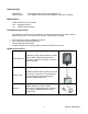
Antenna Installation
Screw the directional antenna onto the coaxial connector on the side of the enclosure until it is
snug. Screw the second antenna onto the second unit.
Test Setups
There are three scales of test setups from basic to thorough.
Bare Minimum Test
Simply apply power to both units and observe the red RX LED in each unit. If both RX LEDs are
blinking, the units are communicating with each other.
Medium Scale Test
This test should consist of a means to control (switch) power to each input independently, thereby
providing a means to switch each relay in the other unit. One way to perform this test would be to
have eight twisted pairs of wire at least 12 inches with each wire end stripped, then connect each
twisted pair to an input. Tighten each screw terminal down onto the stripped wire end until all
eight connections are completed, then route the twisted pair bundle through the gland. Re-install
the removable terminal block onto the input header. Apply power to both units, then apply a
voltage to each input pair one at a time and listen for the relays in the other unit to click, following
the input status of the first unit.
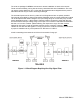
Thorough Scale Test
Using an I/O utility accessory with switches, screw terminals and LEDs such as the TAD8-16, you
could wire up the power supply return to the “B” side of each input, and the power supply positive
to one side of each switch. Connect the other side of each of the eight switches to the “A” side of
each input. Then wire the power supply return to the cathode of each of the eight LEDs and
connect the power supply positive to the common “C” terminal of each relay. As a final set of
connections for the first unit, connect the normally open “NO” contact terminal of each relay to the
anode of each LED on the accessory board.
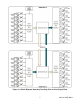
On the second unit, wire up the terminal boards with the power supply positive at each relay
common and the power supply return to each “B” input. Then make a one-to-one connection
between each NO relay contact and each “A” input.
Power on both units and toggle each switch to perform a “round-trip” test. Each switch that gets
toggled into the first unit should control the corresponding relay in the second unit. When the
relay in the second unit switches, it will switch power to the input of the second unit, which will
then switch the corresponding relay in the first unit.
Verify Wireless Connection
Make sure that the green LED is illuminated and that the red LED is blinking in each unit.
The signal strength of the antenna can be affected by various things. If possible, mount the units
as high as possible within line of sight. If the signal passes from building to building, installing the
units near a window can help maintain signal strength. High gain antennas are also available
which can increase the gain up to 11dBi. Consult factory.