
User manual


Manual WWP-IIRO-8
4
Table of Contents
Chapter 1: Introduction ...........................................................................................................................5
Features...................................................................................................................................................5
Applications............................................................................................................................................5
Functional Description ........................................................................................................................5
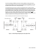
Figure 1-1: Block Diagram Depicting One-Way Signal Flow.................................................6
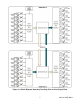
Figure 1-2: Block Diagram Depicting Two-Way (Pair of Units) Signal Flow .....................7
Ordering Guide ......................................................................................................................................8
Included with your board....................................................................................................................8
Optional Accessories...........................................................................................................................8
Chapter 2: Installation..............................................................................................................................9
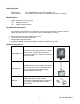
Figure 2-1: Module with the lid open and terminal blocks identified..................................9
Power........................................................................................................................................................9
Antenna Installation ...........................................................................................................................10
Test Setups...........................................................................................................................................10
Bare Minimum Test.........................................................................................................................10
Medium Scale Test..........................................................................................................................10
Thorough Scale Test ......................................................................................................................10
Verify Wireless Connection..............................................................................................................10
Figure 2-2: Input terminal block signal connection locations ............................................11
Figure 2-3: Relay terminal block signal arrangements.........................................................11
Chapter 3: Hardware Details ................................................................................................................12
Option Selections................................................................................................................................12
Filter Response Jumpers..................................................................................................................12
Figure 3-1: Option Selection Map ...................................................................................................12
Table 3-1: Input Filter Jumper Selections.....................................................................................12
Chapter 4: Connector Pin Assignments ...........................................................................................13
Table 4-1: Screw Terminal Connections.......................................................................................13
Chapter 5: Specifications......................................................................................................................14
General...................................................................................................................................................14
Power Requirements..........................................................................................................................14
900 MHz Radio .....................................................................................................................................14
900 MHz Antenna.................................................................................................................................14
Isolated Inputs .....................................................................................................................................14
Relay Outputs.......................................................................................................................................15
Environmental......................................................................................................................................15
Customer Comments .............................................................................................................................16