
User manual


Manual WWP-IIRO-8
9
Chapter 2: Installation
Prior to installing the pair into their final locations, it is recommended you bench test the units side
by side to become familiar with their response times, major features and I/O interfaces.
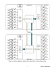
Gain access to the inside of the enclosure by removing the four lid screws, then set the lid and
these screws aside.
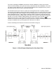
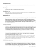
This is what you should see:
Figure 2-1: Module with the lid open and terminal blocks identified
Power
If you ordered two of the optional accessory PWR-ACDC-12V along with the WWP-IIRO-8, they
ship pre-wired into the appropriate screw terminals.
If you didn’t order the optional power supply, you’ll need to provide a DC power source between
7.5V and 15V. Carefully pull up on the input removable screw terminal board to remove it. Route
your power supply wires through the gland on the right and make the connections referring to the
connector pin assignments in Chapter 5.