ACCES I/O PRODUCTS INC 10623 Roselle Street, San Diego, CA 92121 TEL (858)550-9559 FAX (858)550-7322 MODEL PCI-COM422/4 USER MANUAL FILE: MPCICOM422-4.
Notice The information in this document is provided for reference only. ACCES does not assume any liability arising out of the application or use of the information or products described herein. This document may contain or reference information and products protected by copyrights or patents and does not convey any license under the patent rights of ACCES, nor the rights of others. IBM PC, PC/XT, and PC/AT are registered trademarks of the International Business Machines Corporation. Printed in USA.
Warranty Prior to shipment, ACCES equipment is thoroughly inspected and tested to applicable specifications. However, should equipment failure occur, ACCES assures its customers that prompt service and support will be available. All equipment originally manufactured by ACCES which is found to be defective will be repaired or replaced subject to the following considerations. Terms and Conditions If a unit is suspected of failure, contact ACCES' Customer Service department.
Table of Contents Chapter 1: Introduction . . . . . . . . . . . . . . . . . . . . . . . . . . . . . . . . . . . . . . . . . . . . . . 1-1 RS422 Balanced Mode Operation . . . . . . . . . . . . . . . . . . . . . . . . . . . . . . . . . . . . . . . . . COM Port Compatibility . . . . . . . . . . . . . . . . . . . . . . . . . . . . . . . . . . . . . . . . . . . . . . . . . . Communication Mode . . . . . . . . . . . . . . . . . . . . . . . . . . . . . . . . . . . . . . . . . . . . . . . . . . . Baud Rate Ranges .
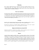
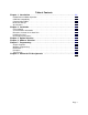
List of Figures Figure 1-1: PCI-COM422/4 Block Diagram . . . . . . . . . . . . . . . . . . . . . . . . . . . . . . . . Page 1-3 Figure 3-1: Simplified Termination Schematic . . . . . . . . . . . . . . . . . . . . . . . . . . . . . . Page 3-1 Figure 3-2: PCI-COM422/4 Option Selection Map . . . . . . . . . . . . . . . . . . . . . . . . . . . Page 3-3 List of Tables Table 5-1: Baud Rate Divisor Values . . . . . . . . . . . . . . . . . . . . . . . . . . . . . . . . . . . . .
Chapter 1: Introduction The PCI-COM422/4 Serial Interface Card was designed for effective transmission in RS422 (EIA422) protocol. The card is 6.1 inches long and may be installed in PCI-bus slots of IBM PC or compatible computers. The card features four independent, asynchronous RS422 serial ports, type 16550 buffered UARTs, and, for Windows compatibility, automatic control to transparently enable/disable the transmission drivers. There are two I/O connector options.
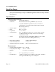
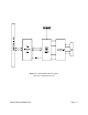
PCI-COM422/4 Manual Baud Rate Ranges The card has capability for two baud rate ranges and you can select which you wish to use on a port-by-port basis. One range is for up to 115,200 baud applications and the other is up to 460,800 baud applications. Specifications Communications Interface • • I/O Connection: Serial Ports: 9-pin D-sub connectors Four shielded male D-sub 9-pin IBM AT style connectors compatible with RS422 specifications.
Figure 1-1: PCI-COM422/4 Block Diagram (Only One Serial Channel Shown) Manual MPCICOM422-4.
PCI-COM422/4 Manual Page 1-4 Manual MPCICOM422-4.
Chapter 2: Installation The software provided with this card is contained on either one CD or multiple diskettes and must be installed onto your hard disk prior to use. To do this, perform the following steps as appropriate for your software format and operating system. Substitute the appropriate drive letter for your CD-ROM or disk drive where you see d: or a: respectively in the examples below. CD Installation DOS/WIN3.x 1. 2. 3. 4. Place the CD into your CD-ROM drive.
PCI-COM422/4 Manual To copy the files on the master diskette to your hard disk, perform the following steps. 1. Place the master diskette into a floppy drive. 2. Change the active drive to the drive that has the diskette installed. For example, if the diskette is in drive A, type ??? . 3. Type ???????? and follow the on-screen prompts. Directories Created on the Hard Disk The installation process will create several directories on your hard disk.
SAMPLES Samples for using ACCES32.DLL are provided in this directory. Using this DLL not only makes the hardware programming easier (MUCH easier), but also one source file can be used for both Windows 95/98 and WindowsNT. One executable can run under both operating systems and still have full access to the hardware registers. The DLL is used exactly like any other DLL, so it is compatible with any language capable of using 32-bit DLLs.
PCI-COM422/4 Manual Findbase.exe DOS utility to determine an available base address for ISA bus , non-Plug-n-Play cards. Run this program once, before the hardware is installed in the computer, to determine an available address to give the card. Once the address has been determined, run the setup program provided with the hardware to see instructions on setting the address switch and various option selections. Poly.exe A generic utility to convert a table of data into an nth order polynomial.
Optional model PCI-COM422/4S1 has connectors for two of the four ports and includes a second mounting bracket which provides connections for two more ports. That companion mounting bracket must be mounted in an adjacent position because ribbon cables are used to mate those two connectors via headers on the card. If you are using Windows95/98, your operating system should detect the new hardware and prompt you for the installation CD.
PCI-COM422/4 Manual Page 2-6 Manual MPCICOM422-4.
Chapter 3: Option Selection To help you locate the jumpers described in this section, refer to Figure 3-2, Option Selection Map at the end of this section. Operation of the serial communications section is determined by jumper installation as described in the following paragraphs. Terminations A transmission line should be terminated at the receiving end in its characteristic impedance.
PCI-COM422/4 Manual Interrupts Please note that, in Windows NT, changes must be made to the system registry to support IRQ sharing. The following is excerpted from "Controlling Multiport Serial I/O Cards" provided by Microsoft in the MSDN library, documentid:mk:@ivt:nt40res/D15/S55FC.HTM, also available in the WindowsNT Resource Kit. The text enclosed in brackets ("[ ]") denotes a comment by ACCES. The Microsoft serial driver can be used to control many dumb multiport serial cards.
Figure 3-2: PCI-COM422/4 Option Selection Map Manual MPCICOM422-4.
Chapter 4: Address Selection The PCI-COM422/4 card uses four separate address spaces. COM A occupies 16 consecutive register locations and COM B, COM C, and COM D each occupy eight consecutive register locations. PCI architecture is Plug-and-Play. This means that the BIOS or Operating System determines the resources assigned to PCI cards rather than you selecting those resources with switches or jumpers. As a result, you cannot set or change the card's base address.
Chapter 5: Programming Sample Programs There are sample programs provided with the PCI-COM422/4 card in C, Pascal, QuickBASIC, and several Windows languages. DOS samples are located in the DOS directory and Windows samples are located in the WIN32 directory. Windows Programming The PCI-COM422/4 card installs into Windows as COM ports. Thus the Windows standard API functions can be used. In particular: ? CreateFile() and CloseHandle() for opening and closing a port.
PCI-COM422/4 Manual On the PCI-COM422/4 card, the UART clock frequency is 1.8432 MHz. On the next page is a table for the popular divisor frequencies: Baud Rate Divisor Max Diff.
The C command to set the UART for an 8-bit word, no parity, and one stop bit is: outportb(BASEADDR +3, 0x03) The final initialization step is to flush the receiver buffers. You do this with two reads from the receiver buffer at Base Address +0. When done, the UART is ready to use. Reception Reception can be handled in two ways: polling and interrupt-driven. When polling, reception is accomplished by constantly reading the Line Status Register at Base Address +5.
PCI-COM422/4 Manual Transmission RS422 transmission is simple to implement. The AUTO feature of the PCI-COM422/4 card automatically enables the transmitter when data is ready to send so no software enabling is required. The following software example is for non-AUTO operation. To transmit a string of data, the transmitter must first check Bit 5 of the Line Status Register at Base Address +5. That bit is the transmitter-holding-register-empty flag. If it is high, the transmitter has sent the data.
Chapter 6: Connector Pin Assignments The popular 9-pin D subminiature connector is used for interfacing to communication lines. The connector is equipped with 4-40 threaded standoffs (female screw lock) to provide strain relief. Pin No. RS422 Signals 1 Rx- 2 Tx+ 3 Tx- 4 5 GND Ground 6 7 8 9 Rx+ Table 6-1: Connector Pin Assignments Manual MPCICOM422-4.
PCI-COM422/4 Manual Page 6-2 Manual MPCICOM422-4.
Customer Comments If you experience any problems with this manual or just want to give us some feedback, please email us at: manuals@accesioproducts.com.. Please detail any errors you find and include your mailing address so that we can send you any manual updates. 10623 Roselle Street, San Diego CA 92121 Tel. (619)550-9559 FAX (619)550-7322 www.accesioproducts.