0623 Roselle Street, San Diego, CA 92121 contactus@accesio.com • • (858) 550-9559 • FAX (858) 550-7322 www.accesio.com MODELS PCI-IDI-XX SERIES USER MANUAL File: mpci-idi-48.
Notice The information in this document is provided for reference only. ACCES does not assume any liability arising out of the application or use of the information or products described herein. This document may contain or reference information and products protected by copyrights or patents and does not convey any license under the patent rights of ACCES, nor the rights of others. IBM PC, PC/XT, and PC/AT are registered trademarks of the International Business Machines Corporation. Printed in USA.
Warranty Prior to shipment, ACCES equipment is thoroughly inspected and tested to applicable specifications. However, should equipment failure occur, ACCES assures its customers that prompt service and support will be available. All equipment originally manufactured by ACCES which is found to be defective will be repaired or replaced subject to the following considerations. Terms and Conditions If a unit is suspected of failure, contact ACCES' Customer Service department.
Table of Contents Chapter 1: Introduction................................................................................................. 5 Table 1-1: Model Versions ....................................................................................... 6 Specification .............................................................................................................. 7 Figure 1-1: Block Diagram ......................................................................................
Chapter 1: Introduction Features • • • • • Individually-Isolated AC/DC Inputs for up to Three 16-Bit Groups, 48 total. Reverse Polarity protection AC Filtering Optical Isolation, Channel-to-Channel and Channel-to-Host PC. Change-of-State detection (certain models). Description This series of cards provide as many as 48 optically-isolated inputs for AC/DC signals with Change-ofState (COS) Detection capability. Each input is reverse polarity protected and rectified by photo-coupler diodes.
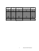
MODEL 16A 16AC 32A 32AC 48A 48AC 16B 16BC 32B 32BC 48B 48BC No.
Specification Digital Isolated Inputs Number of inputs: 16, 32, or 48 Type: Non-polarized, optically isolated from each other and from the computer (CMOS compatible) Voltage Range xxA: Logic Low: 0 to 1.5VDC or AC Rms (40 to 10kHz) Logic High: 3 to 31VDC or AC Rms (40 to 10kHz) xxB: Logic Low: 0 to 5VDC or AC Rms (40 to 10kHz) Logic High: 11 to 60VDC or AC Rms (40 to 10kHz) Isolation: Optically Isolated channel-to-ground or channel-to channel * see note Input Resistance xxA: 1.
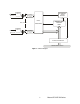
ISOLATED INPUT 0 CURRENT LIMITER CHANGE-OFSTATE DETECT Vcc JUMPER SELECTABLE FILTER IRQ EN INPUT INPUTS 0-47 CURRENT LIMITER ISOLATED INPUT 47 ADDRESS AND CONTROL LOGIC REGISTERS Vcc JUMPER SELECTABLE FILTER IRQ PCI BUS INTERFACE COMPUTER PCI BUS Figure 1-1: Block Diagram 8 Manual PCI-IDI-XX Series
Chapter 2: Installation A printed Quick-Start Guide (QSG) is packed with the card for your convenience. If you’ve already performed the steps from the QSG, you may find this chapter to be redundant and may skip forward to begin developing your application. The software provided with this card is on CD and must be installed onto your hard disk prior to use. To do this, perform the following steps as appropriate for your operating system.
Hardware Installation 1. 2. 3. 4. 5. 6. 7. 8. 9. Do not install card into the computer until the software has been fully installed. Turn OFF computer power AND unplug AC power from the system. Remove the computer cover. Carefully install the card in an available 5V or 3.3V PCI expansion slot (you may need to remove a backplate first). Inspect for proper fit of the card and tighten screws. Make sure that the card mounting bracket is properly screwed into place and that there is a positive chassis ground.
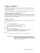
Chapter 3: Option Selection Each channel has a jumper configurable filter option. NO FILTER FILTER 3.90" FLT47 FLT31 FLT32 FLT16 FLT 0 FLT15 6.90" Figure 3-1: Option Selection Map Filter Response Switch Jumpers are used to select input filtering on a channel-by-channel basis (see Figure 3-1). When jumper FLT0 is installed, filtering is introduced for input bit 0, FLT1 for bit 1, and so on. The tables below describe filtering for Port 0.
Chapter 4: Address Selection This card uses I/O addresses offset from the base address assigned by the PCI bus. The address spaces are defined in the Programming section of this manual. PCI architecture is Plug-and-Play. This means that the BIOS or Operating System determines the resources assigned to PCI cards rather than the user selecting these resources with switches or jumpers. As a result, you cannot set or change the card’s base address or IRQ level.
Chapter 5: Programming The base address is assigned by the computer system during installation and will fall on an eight byte boundary.
Write Base + 7: COS Enable/Disable Register Bit 7 Bit 6 Bit 5 Bit 4 Bit 3 Bit 2 Bit 1 Bit 0 IRQ Enable/ Disable N/A N/A N/A N/A N/A N/A N/A 14 Manual PCI-IDI-XX Series
Chapter 6: Connector Pin Assignments Isolated inputs are connected to the card via a 50-pin HEADER type connector. There are three connectors named PORT0, PORT1, and PORT2. The table below describes PORT0. PORT1 and PORT2 are identical pinouts. Pin 50 is located toward the Jumpers, while Pin 1 is located near connection to Motherboard.
Customer Comments If you experience any problems with this manual or just want to give us some feedback, please email us at: manuals@accesio.com. Please detail any errors you find and include your mailing address so that we can send you any manual updates. 10623 Roselle Street, San Diego CA 92121 Tel. (858)550-9559 FAX (858)550-7322 www.accesio.