ACCES I/O PRODUCTS INC 10623 Roselle Street, San Diego, CA 92121 TEL (619)550-9559 FAX (619)550-7322 MODEL AIM-16 USER MANUAL FILE: MAIM-16.
Notice The information in this document is provided for reference only. ACCES does not assume any liability arising out of the application or use of the information or products described herein. This document may contain or reference information and products protected by copyrights or patents and does not convey any license under the patent rights of ACCES, nor the rights of others. IBM PC, PC/XT, and PC/AT are registered trademarks of the International Business Machines Corporation. Printed in USA.
Warranty Prior to shipment, ACCES equipment is thoroughly inspected and tested to applicable specifications. However, should equipment failure occur, ACCES assures its customers that prompt service and support will be available. All equipment originally manufactured by ACCES which is found to be defective will be repaired or replaced subject to the following considerations. Terms and Conditions If a unit is suspected of failure, contact ACCES' Customer Service department.
Table of Contents Notice . . . . . . . . . . . . . . . . . . . . . . . . . . . . . . . . . . . . . . . . . . . . . . . . . . . . . . . . . . . . . . iii Warranty . . . . . . . . . . . . . . . . . . . . . . . . . . . . . . . . . . . . . . . . . . . . . . . . . . . . . . . . . . . iv Chapter 1: Introduction . . . . . . . . . . . . . . . . . . . . . . . . . . . . . . . . . . . . . . . . . . . . . . 1-1 Specifications . . . . . . . . . . . . . . . . . . . . . . . . . . . . . . . . . . . . . . . . . . . . . . .
List of Figures Figure 1-1: AIM-16 Block Diagram . . . . . . . . . . . . . . . . . . . . . . . . . . . . . . . . . . . . . . . . . . . . 1-3 Figure 2-1: Use of CAB-37Y Cables . . . . . . . . . . . . . . . . . . . . . . . . . . . . . . . . . . . . . . . . . . 2-6 Figure 2-2: AIM-16 Option Selection Map . . . . . . . . . . . . . . . . . . . . . . . . . . . . . . . . . . . . . 2-11 List of Tables Table 2-1: AIM-16 Gain Table . . . . . . . . . . . . . . . . . . . . . . . . . . . . . . . . . . . . . . . . . . .
Chapter 1: Introduction Analog Input Multiplexer, Model AIM-16, is installed external to the computer. The AIM-16 accepts, preamplifies, and multiplexes up to 16 analog input signals before passing them to an analog-to-digital converter typically located in an I/O slot in a PC/XT/AT type host computer. This allows direct sensor interface without jeopardizing the quality of gathered data.
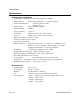
AIM-16 Manual Specifications Analog Inputs and Outputs • • • • • • • • • • • • • • • • • • • Input Channels: 16 Differential Analog Input Channels per AIM-16. Output Channels: Analog Output assignable to 1 of 8 Output Channels. Common Mode Rejection: 125 db for gains above 100. 90 db for gain = 1. Output Rating: 5mA at ±10VDC or ±5VDC. Gain Nonlinearity: ±0.005%. Temp. Coefficient: 5 ppm/ °C. Overvoltage: Continuous: 70V peak-to-peak, 35VDC. Sensors: Thermocouples, with break detect provided.
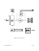
Figure 1-1: AIM-16 Block Diagram Manual MAIM-16.
AIM-16 Manual Page 1-4 Manual MAIM-16.
Chapter 2: Installation The software provided with this card is contained on either one CD or multiple diskettes and must be installed onto your hard disk prior to use. To do this, perform the following steps as appropriate for your software format and operating system. Substitute the appropriate drive letter for your CD-ROM or disk drive where you see d: or a: respectively in the examples below. CD Installation DOS/WIN3.x a. b. c. d. Place the CD into your CD-ROM drive.
AIM-16 Manual To copy the files on the master diskette to your hard disk, perform the following steps. a. Place the master diskette into a floppy drive. b. Change the active drive to the drive that has the diskette installed. For example, if the diskette is in drive A, type a:K. c. Type installK and follow the on-screen prompts. Directories Created on the Hard Disk The installation process will create several directories on your hard disk.
SAMPLES Samples for using ACCES32.DLL are provided in this directory. Using this DLL not only makes the hardware programming easier (MUCH easier), but also one source file can be used for both Windows 95/98 and WindowsNT. One executable can run under both operating systems and still have full access to the hardware registers. The DLL is used exactly like any other DLL, so it is compatible with any language capable of using 32-bit DLLs.
AIM-16 Manual Findbase.exe DOS utility to determine an available base address for ISA bus , non-Plug-n-Play cards. Run this program once, before the hardware is installed in the computer, to determine an available address to give the card. Once the address has been determined, run the setup program provided with the hardware to see instructions on setting the address switch and various option selections. Poly.exe A generic utility to convert a table of data into an nth order polynomial.
Input connections are labeled "+", "GND", and "-". Shields should be connected to the "GND" terminal if not grounded at the sensor end. Three-wire RTD connections can be made as follows: connect RTD wires +V and +I to the "+" terminal on the AIM-16, connect RTD wire -V to the "-" terminal, and connect RTD wire -I to the "GND" terminal. To assure that there is minimum susceptibility to EMI, proper EMI cabling techniques (twisted-pair wiring and, in extreme cases shielded wiring) must be used on input wiring.
AIM-16 Manual Figure 2-1: Use of CAB-37Y Cables Page 2-6 Manual MAIM-16.
Option Selection AIM-16 options are selected either by the DIP switch for High Offset and Gain setup, or by installing plug-in jumpers or solder shunts between labeled points for other options. Refer to Option Selection Map for the location of the jumper, short, and switch selections discussed below. The SETMUX program included with AD12-8 is a special program to assist you in setting up the card. The program uses a menu and illustrations to make it easy to select jumper and switch choices.
AIM-16 Manual Combination of Gain Mode In instances where less than three digital input control lines are available for setting programmable gains, a combination of manual and programmable gain may be used. One programmable line gives selection of two gains; two lines gives four available gains; and three the entire eight. The switch locations marked GP0, GP1,and GP2 correspond to digital input bits G0, G1, and G2 respectively.
Channel Selection This option selects which AD12-8 A/D input channel will be used by the AIM-16. Install a jumper in a one of the positions labeled OV0 through OV7. ("OV" stands for output voltage.) This channel must not be used by any other AIM-16, or reference junction in the system. Usually, the first AIM-16 in a system is set to OV0. If a second AIM-16 is to be used, you can set it's jumper to OV1, a third to OV2, etc.
AIM-16 Manual RTD Sensor Selection To configure a channel for RTD operation, install shorts in two selection points both labeled R"n", where "n" is the channel number. These points are all located near the edge of the board furthest from the connectors in the screw-terminal input area. RTD Output Offset For a board dedicated to RTD sensors, a negative output offset may be selected by installing a jumper in the OFST position of the programming point labeled "OFST STD".
Figure 2-2: AIM-16 Option Selection Map Manual MAIM-16.
AIM-16 Manual Calibration and Test All ACCES cards are calibrated prior to shipment. However, periodic calibration of AIM-16 is recommended to retain full accuracy. The calibration interval depends to a large extent on the type of service that the card is subjected to. For environments where there are frequent large changes of temperature and/or vibration, a three-month interval is suggested. For laboratory or office conditions, six months to a year is acceptable.
Chapter 3: Software The AIM-16 does not have software included with it, as software for a system is largely dependent upon the A/D card used. The AD12-8 A/D card has a full range of software included with it that includes support for the AIM-16 as follows. See "Directories Created on the Hard Disk" in the Installation section for a complete software description.
AIM-16 Manual Page 3-2 Manual MAIM-16.
Chapter 4: Sensor Interface Before attempting to program or set up the AIM-16, the overall system of which the AIM-16 is a part should be defined. The AIM-16 provides the system's interface to the various sensors which supply data. We suggest that you make a list of sensors by type and location. Where practical, sensors of one type should be grouped on the AIM-16 card to simplify programming.
AIM-16 Manual Considerations for RTD Sensors Three-wire connection may be applied to an RTD sensor by adding two shorts per channel for each sensor served. The locations for these shorts are labelled R0 through R15. For example, install two shorts in the two locations labeled R2 if an RTD sensor is used at channel 2. For extended range and resolution of measurements, it is common practice in RTD processing to offset the sensor output in a negative direction.
Considerations for Current Inputs The AIM-16 card has provisions for reading input current. Reserved space and board connections are available for 16 precision resistors. To utilize this provision, it is only necessary to install a resistor of the proper value and set the gain appropriately for each channel to be used for current input. When all inputs are designated for sensing 4-20mA current, it is beneficial to increase resolution by providing offset.
AIM-16 Manual Page 4-4 Manual MAIM-16.
Appendix A: Cabling and Connector Information Input Connector Pin Assignments Connections are made to the AIM-16 card via a 37-pin D type connector. The female mating connector can be a Cannon #DC-37S for soldered connections. Alternatively, insulation-displacement flat cable types such as AMP #745242-1 may be used. Pin 1 2 3 4 5 6 7 8 9 10 11 12 13 14 15 16 17 18 19 20 21 22 23 24 25 26 27 28 29 30 31 32 33 Name +VS unused G0 unused G1 G2 A0 A1 A2 A3 PWR GND unused unused unused unused unused unused L.L.
AIM-16 Manual 34 35 36 37 CH3 IN CH2 IN CH1 IN CH0 IN Chl 3 Analog Output Chl 2 Analog Output Chl 1 Analog Output Chl 0 Analog Output Table A-1: Connector Pin Assignments Page A-2 Manual MAIM-16.
Customer Comments If you experience any problems with this manual or just want to give us some feedback, please email us at: manuals@accesioproducts.com.. Please detail any errors you find and include your mailing address so that we can send you any manual updates. 10623 Roselle Street, San Diego CA 92121 Tel. (619)550-9559 FAX (619)550-7322 www.accesioproducts.