TABLE OF CONTENTS INTRODUCTION ................................................................................................................................. 3 A DETAILED INTRODUCTION FOR NOVICES....................................................................................... 5 Cable Connections........................................................................................................................... 5 Listening to the Factory sounds .................................................
VIRUS Owner’s Manual Twin Mode................................................................................................................................ 39 Chorus ...................................................................................................................................... 40 Delay ........................................................................................................................................ 41 Punch ....................................................
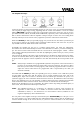
INTRODUCTION Dear Virus Owner, Congratulation on your choice, the new Virus. You have purchased a cutting-edge synthesizer that comes fully loaded with several revolutionary features. Here are just a few of the highlights: • The Virus delivers the sound characteristics and tone of traditional analog synthesizers - for instance the Prophet 5 or Memorymoog to name just two popular examples of the species - in a previously unparalleled level of quality and handling ease.
VIRUS Owner’s Manual • And last but not least, you have all of these features without the major hassles inherent in vintage analog synthesizers. Compared with its behemoth predecessors, the Virus is exceptionally compact, light-weight and dependable. You never have to contend with lengthy warm-up periods and pitch instability due to temperature changes. (You might even feel that the Virus is TOO small. Those massive analog beasts certainly had a stunning visual effect, especially on stage.
A DETAILED INTRODUCTION FOR NOVICES This section provides deliberate, step-by-step guidelines on operating and handling the Virus for those of you who are new to the world of synthesizers and MIDI. The following covers basics such as how to connect the Virus to an AC power supply, your MIDI system and your audio system. Then we will guide you through a series of experiments designed to demonstrate the different functional groups, their control features and the tasks they execute.
VIRUS Owner’s Manual Listening to the Factory Sounds The program memory of the Virus was loaded with sound programs (SINGLE PROGRAMs) and sound combinations (MULTI PROGRAMs) before it left the factory. To hear the SINGLE PROGRAMs (and gain an initial impression of the possibilities your new instrument has to offer in terms of sounds), first make sure your MIDI source is sending on MIDI Channel 1. Press the SINGLE button. A number, a letter, number and name appear in the display.
The Amplifier Envelope Long-term exposure to this sound will definitely grate on your nerves, so let’s get started with changing it into a signal you might enjoy hearing, beginning with the volume characteristics. Locate the section labeled AMPLIFIER at the bottom right of the control feature panel of the Virus. Here you can see five pots labeled ATTACK, DECAY, SUSTAIN, TIME and RELEASE, respectively.
VIRUS Owner’s Manual FALL), then the level drops off at an increasing rate towards the minimum level much in the manner you just experienced with the DECAY pot; If you turn the pot clockwise to the right (towards RISE), the level rises at an increasing rate to maximum and remains there until you release the key.
Now locate the FILT 1 MODE switch which is also located in the FILTERS section. It enables you to select a filter operating mode from the four available options: • LP: the low pass filter we have just discussed. • HP: the high pass filter which works in the opposite manner of the low pass filter: It suppresses the lower frequencies in a signal and lets the higher frequencies pass.
VIRUS Owner’s Manual determined manually. And it is definitely not always desirable that the filter frequency is brought to the maximum level. Consequently, you need a tool that limits the effective range of the filter. This is why we equipped the Virus with a control labeled ENV AMOUNT (short for Envelope Amount).
The Saturation Stage In the signal chain of the Virus, Filter 1 is followed by a saturation stage. It enables you to add overtones to the filtered signal via distortion. Locate and press the button labeled SATURATION in the FILTERS section. The display will read "SATURATION CURVE OFF", which means exactly what it says. With the VALUE buttons or the VALUE pot, you can now select from a number of saturation/distortion curves. Once you have selected a curve, the SATURATION button LED illuminates.
VIRUS Owner’s Manual chain. When you turn the FILTER BALANCE pot clockwise, Filter 1 is blended out of the signal chain until at the far right position only Filter 2 is active and audible. The term used to describe the efficiency of a filter is „slope.“ The unit of measurement is the so-called filter pole: the more poles a filter has, the greater its slope. Each filter in the Virus normally features 2 poles.
The final parameter we’ll discuss for the time being is FILTER ROUTING. This feature offers several filter routing options which allow you to operate the filters in series, i.e. patch one after the other in the signal chain, or in parallel, which means side by side in the signal chain: SER 4 The filters are switched in series; with two poles each, both filters have the same slope for a total of four filter poles.
VIRUS Owner’s Manual The First Oscillator To this point, we have turned our attention exclusively to sound-shaping functions and have always started with the same basic material: a so-called sawtooth wave. This waveshape is especially well-suited as a neutral starting point as it contains all of the so-called natural scale of overtones, which give the filter plenty of quality material to work with.
numbered tones, i.e. the first (the root note that determines the pitch), third, fifth, and so forth. By turning the SHAPE pot from the sawtooth control range towards the pulse control range, you are actually dialing every other overtone out of the mix, which explains why the sound becomes thinner. You can continue modifying the sound by reducing the symmetrical width of the pulse wave.
VIRUS Owner’s Manual oscillators are the source of this effect. The oscillators of the Virus oscillate freely, consequently every time you play a note, the phase constellation between the two oscillators is different. For now, leave the OSC BAL POT at the center position (12 o’clock). You are already familiar with Oscillator 1’s SHAPE and WAVE SEL/PW pots. These functions are identical for Oscillator 2, so we won’t go into detail on them again.
The MIXER Section You have already come across two parameters of the MIXER section: OSC BAL determines the mix ratio between Oscillators 1 and 2; in the left half of its control range, OSC VOL determines the master volume of the oscillator mix. In the right half of the control range from the center position to the far right, OSC VOL increases the saturation intensity when a SATURATION curve has been activated.
VIRUS Owner’s Manual The LFOs When you first started this series of experiments with sounds, we promised that many of the functions the Virus can be „programmed“ so that they are executed automatically. You have already learned how to control the volume and cutoff frequencies of both filters as well as the pitch and intensity of the frequency modulation of Oscillator 2 via „preprogrammed“ envelopes.
Here are the definitions for the modulation targets: OSC 1 refers to the frequency of oscillator 1 OSC 2 refers to the frequency of oscillator 2 PW 1+2 means that the pulse widths of both oscillators are controlled in unison RESO 1+2 refers to the resonances of both filters. Please keep in mind that although each set of these parameters is assigned a common modulation intensity, you can still dial in different sound-shaping settings manually.
VIRUS Owner’s Manual You may have gathered that the LFOs of the Virus are polyphonic: If several notes are played simultaneously, these are controlled by dedicated LFOs, each with a slightly varied rate. This effect livens up the sound of chords, especially when they are sustained. To enhance this effect, activate the LFO 1 KEY FOLLOW button. This function enables you to control the rate of the LFOs via the pitch, or more accurately, via the MIDI note number, so that higher notes generate faster LFO rates.
LFO 3 You will find another LFO in the EDIT menu. In comparison to the others, this LFO is a stripped-down version. Basically all it does is control the frequencies of the two oscillators. It is primarily used to generate vibrato independently of the main LFOs. You can control its effect on the oscillators via the modulation wheel. For more information on this LFO, refer to the detailed section of the manual.
VIRUS Owner’s Manual Velocity Velocity is one of the preferred modulation sources of keyboard players. In the Virus you have ten modulation targets available for Velocity. Locate the VELOCITY section in the CTRL menu. There you will find the modulation intensities for OSC 1 SHAPE OSC 2 SHAPE PULSE WIDTH FM AMOUNT FILT 1 ENV AMT FILT 2 ENV AMT RESONANCE 1 RESONANCE 2 VOLUME PANORAMA which you can manipulate independently of one another in the familiar bipolar control range.
If the delay is less than approx. 10 milliseconds, than the effect is called flanging or a flanger effect rather than chorus. In this case feedback is even more significant because it generates resonances that can be modulated and is thus yet another source of radical sound effects. If you determine high feedback values, you can clearly hear how the two sides of the signal are modulated differently - in reverse phase - by the LFO. Locate the parameter group CHORUS in the EDIT menu.
VIRUS Owner’s Manual COMPREHENSIVE OVERVIEW This section of the manual deals with the basic operating modes of the Virus: SINGLE MODE and MULTI MODE. Then we’ll take a look at the general handling and operation guidelines for the Virus. Finally you will be presented with a comprehensive list of all functions in the Virus with a brief explanation of each function. OPERATING MODES In the Virus you can select from two basic operating modes, SINGLE MODE and MULTI MODE.
OPERATING CONVENTIONS Parameter Selection and Data Entry In the Virus, we distinguished between two types of parameters. On the one hand, it features parameters that are essential in generating or synthesizing sounds, on the other hand it has sound parameters and organizational parameters that are more of a peripheral nature.
VIRUS Owner’s Manual The PARAMETER buttons provide access to the parameters in the EDIT, CTRL and local menus. Simply press the corresponding button to scroll through the parameters in the desired direction. If you press and hold a PARAMETER button and simultaneously press the other PARAMETER button, the menu scrolls through groups in the direction of the button you are holding down so that you can comfortably select from all oscillator-related parameters and all filter-related parameters.
In RELATIVE Mode, the triangle to the right of the number indicates if the VALUE knob coincides with the parameter value (solid triangle) or not (blank triangle). When a menu is active, two display options are available for parameters with a dedicated knob. These can be selected under the menu item KNOB DISPLAY in the CTRL menu: OFF Knob movements are not displayed; the current contents of the display remain intact when you turn a knob.
VIRUS Owner’s Manual Operating Modes In the Virus, we distinguished between two basic operating modes: SINGLE MODE and MULTI MODE.
In the Virus, this problem is solved by subdividing its parameters into three Parameter PAGEs for data transmission purposes. Each of these three PAGEs contains up to 128 parameters. A SINGLE PROGRAM consists of the parameters on the first two first PAGEs. Parameters on the first PAGE are assigned to MIDI Controllers and parameters on the second PAGE are sent and received via socalled PolyPressure data.
VIRUS Owner’s Manual THE PARAMETERS The following section lists all parameters in the Virus, each with a brief definition or explanation.
section), including everything from a descending sawtooth to a conventional triangle and on to an ascending sawtooth. KEY FOLLOW Activates a function in which the LFO frequency is controlled via the note number. When EXPERT MODE is active, you have the option of setting the control intensity in the EDIT menu under LFO 1 KEY FOLLOW AMT (see appropriate section).
VIRUS Owner’s Manual KEY TRIGGER Activates the synchronization of the LFOs at the start of a note: The LFO no longer oscillates freely, it restarts its wave cycle at the beginning of each note. With the function KEY TRIG PHASE in the EDIT menu, you can select the position within the wave cycle at which you want the LFO to start oscillating at the start of a note. ENV MODE Same as LFO 1; see paragraph above. AMOUNT This button does not actually control a parameter, it opens a local menu.
2. When the SHAPE value is higher than that of the center position, then WAVE SEL/PW determines the pulse width: At the far left position the pulse width is 50%, at the far right it is 0%, which means the wave no longer oscillates. OSCILLATOR 2 SHAPE Same as OSCILLATOR 1; see paragraph above. WAVE SEL/PW Same as OSCILLATOR 1; see paragraph above. SEMITONE Determines the interval between the second oscillator and the first oscillator: Control range +/-48 semitones, assigned in semitone steps.
VIRUS Owner’s Manual MIXER OSC BAL Determines the balance between the Oscillators 1 and 2 volume level. SUB OSC Determines the volume level of the SubOscillator. OSC VOL This knob has two functions: 1. In the left half of its control range up to the center position (MIDI value 64), OSC VOL determines the master volume of the three oscillators prior to the filter section input. The fourth voice-internal signal source, the Noise Generator, is not affected by the master volume knob OSC VOL.
towards the center position. From the center position towards the far right, Filter 1/Saturation is blended out of the mix so that the signal is routed through Filter 2 only. Consequently, you must set FILTER BALANCE to the center position if you want both filters in series (in equal amounts) in the signal path. CUTOFF 2 Controls the cutoff frequency of Filter 2.
VIRUS Owner’s Manual be manipulated via the parameter TWIN MODE PAN SPREAD (see appropriate section) in the EDIT menu. Regardless of which FILTER ROUTING option you chose, the SATURATION stage is always post-Filter 1. FILT 1 SELECT FILT 2 SELECT This control feature is used to allocate the three knobs RESONANCE, ENV AMOUNT and KEY FOLLOW to the first filter, second filter or both filters. The currently active assignments are indicated by the integrated LEDs.
DECAY Determines the amount of time it takes for the filter envelope to fade out. The higher the DECAY value, the longer it takes for the envelope to fall from its peak level to the SUSTAIN value. SUSTAIN Determines a variable level for the filter envelope at which it remains after the end of the DECAY phase (see appropriate section). The duration of the SUSTAIN phase depends on the TIME value (see appropriate section). TIME Sets the bipolar time parameter for the filter envelope.
VIRUS Owner’s Manual Sound Parameters in the EDIT Menu (Single) EDIT MODE Switches between EXPERT MODE and EASY MODE. Menu parameters that are only available in the EXPERT MODE are identified in the following section by an (EX). OUTPUT PATCH VOLUME Storable master volume for the SINGLE program. Its nominal value is set to 100 so that you have a reserve of 27 volume increments when you are dealing with exceptionally low-level sound settings.
OUT 2 L+R OUT 2 R Both jacks of dual Output 2 (stereo) The right jack of dual Output 2 (mono) OUT 3 L The left jack of dual Output 3 (mono) OUT 3 L+R Both jacks of dual Output 3 (stereo) OUT 3 R The right jack of dual Output 3 (mono) AUX 1 L The left channel of internal Aux 1 (mono) AUX 1 L+R Both channels of internal Aux 1 (stereo) AUX 1 R The right channel of internal Aux 1 (mono) AUX 2 L The left channel of internal Aux 2 (mono) AUX 2 L+R Both channels of internal Aux 2 (stereo) AUX 2 R
VIRUS Owner’s Manual PAN SPREAD Stereo panorama spread of the two TWIN MODE voices. PAN SPREAD also determines the stereo spread of the two filters when the FILTER ROUTING (see appropriate section) option SPLIT is active. LFO PHASE (EX) Shifts the phases of the two TWIN MODE voices’ LFOs relatively. This effect livens up modulations. The value range of -64 to +63 is equivalent to -180 to +177 degrees.
DELAY Controls the delay time of the Chorus. FEEDBACK Controls the amount of feedback in the Chorus. SHAPE (EX) Determines the waveshape of the Chorus LFO. You can select from sine, triangle, sawtooth, pulse, S&H (abb. for: Sample & Hold) and S&G (abb. for: Sample & Glide) waves. DELAY In SINGLE MODE, all Delay settings apply to the SINGLE PROGRAM in the conventional manner and are stored along with the program. However in MULTI MODE, all 16 PARTs access the same Delay effect.
VIRUS Owner’s Manual TIME Controls the delay time in Milliseconds (max. 693ms) CLOCK When you set it to OFF, the absolute delay time is determined in milliseconds. If you select a note value, then the delay time is set to the value of this note. The absolute length of this note value depends on the value entered to CLOCK TEMPO in the global clock generator (refer to this section). In this case, the absolute delay time in milliseconds is ignored.
SHAPE (EX) Determines the waveshape of the Delay LFO. You can select from sine, triangle, sawtooth, pulse, an incremental random modulation (S&H; abb. for Sample & Hold) and a continual random modulation S&G (abb. for: Sample & Glide) waves. PUNCH INTENSITY Here you can influence the attack of the amplifier envelope to enhance the sound with a more percussive, snappy kind of feel. You may have guessed that PUNCH INTENSITY determines the intensity of this effect.
VIRUS Owner’s Manual Negative values generate opposite control intensities. OSCILLATOR 2 WAVE (EX) Selects among of 64 waveshapes. This parameter is identical to WAVE SEL/PW (see appropriate section) when SHAPE (see appropriate section) is set to the left half of its control range. However, in contrast to WAVE SEL/PW, WAVE is always available regardless of the current SHAPE setting.
NOISE VOLUME Controls the level of the Noise Generator. This volume level is independent of the parameter OSC VOL (see appropriate section) FILTERS FILTER 1 ENV POLARITY (EX) Switches back and forth between positive (POS) and negative (NEG) ENV AMOUNTs for Filter 1 (see appropriate section). FILTER 2 ENV POLARITY (EX) Switches back and forth between positive (POS) and negative (NEG) ENV AMOUNTs for Filter 2 (see appropriate section).
VIRUS Owner’s Manual KEYFOLLOW BASE (EX) This feature determines the base note for the filter KEYFOLLOW: When you press the key selected here, the filter frequency you determined manually has priority - i.e. it is not influenced in any manner regardless of the KEY FOLLOW setting (see appropriate section ) for the filters. As the interval between the KEYFOLLOW BASE value and the keys increases as you move up towards the higher end of the keyboard, the influence of KEY FOLLOW increases accordingly.
TRI SYMMETRY (EX) This is a bipolar parameter that influences the shape of the triangle wave: If TRI SYMMETRY is set to 0, the triangle wave oscillates in the conventional manner; as you set increasingly negative values, the symmetry of the wave’s oscillation shifts towards the shape of a descending sawtooth; at increasingly positive values, the symmetry of the wave’s oscillation shifts towards the shape of an ascending sawtooth.
VIRUS Owner’s Manual TRI SYMMETRY (EX) Same as LFO 1; see paragraph above. LFO 3 RATE Determines the speed of the LFO. DESTINATION Determines the modulation destination of the LFO. You can select from: OSC 1 The pitch of Oscillator 1 OSC 1+2 The pitch of both oscillators OSC 2 The pitch of Oscillator 2 PW 1 The pulse width of Oscillator 1 PW 1+2 The pulse width of both oscillators PW 2 The pulse width of Oscillator 2 OSC AMOUNT Controls the modulation intensity of the LFO.
SHAPE (EX) Determines the waveshape of the LFO. You can select from sine, triangle, sawtooth, pulse, S&H (abb. for: Sample & Hold) and S&G (abb. for: Sample & Glide) waves. MODE (EX) Switches back and forth between two LFO operating modes: POLY In polyphonic mode, each of the voices involved is assigned a dedicated LFO. SINGLE In polyphonic mode, all voices are assigned the same LFO. KEY FOLLOW (EX) Controls the intensity of the KEY FOLLOW function - i.e.
VIRUS Owner’s Manual press. The sound program can still be played polyphonically and you can allocate several different filter frequencies and independent envelopes simultaneously (!) to the input signal via the MIDI keyboard. STATIC Instead of the internal sound sources, an external signal source is routed to the filter section.
INPUT BOOST With INPUT BOOST, you can increase the signal level of the two external inputs by up to 36 dB. The signal is boosted in the digital section of the Virus, so the noise level of the analog-digital converter increases automatically. Consequently you should dial in the cleanest, loudest possible signal at the external sound generator. The Virus features a signal level indicator that allows you to monitor the signal level visually: see LED MODE in the CTRL menu.
VIRUS Owner’s Manual Sound Parameters in the CTRL Menu (Single) PART PART ENABLE This PART parameter is a MULTI MODE parameters and is stored along with the current MULTI PROGRAM. Consequently, it is available in MULTI MODE. It is also available in the SINGLE CTRL menu when MULTI SINGLE MODE is active. Why? Because it comes in handy when you are working with sequencers. Switches the MIDI receive mode of a given PART ON and OFF, i.e. enables reception of MIDI data.
PORTAMENTO Determines the amount of time it takes for the pitch to glide from the current note to the next note played. PORTAMENTO is a significant feature of KEY MODE (see paragraph above); the two are closely related. BEND UP Determines the interval of the bend when the Pitch Bender is moved upwards to the full extent of its range. Control range: -64 semitones to +63 semitones. BEND DOWN Determines the interval of the bend when the Pitch Bender is moved downwards to the full extent of its range.
VIRUS Owner’s Manual You can also synchronize the clock generator to the MIDI CLOCK of an external sequencer. The tempo of the clock generator is set globally via CLOCK TEMPO in beats per minute. You have an available control range of 62 to 190 BPM (beats per minute). You can set the rhythmic resolution of the clock generator - in other words, the notes, individually for each involved function (ARPEGGIATOR CLOCK, LFO 1 CLOCK, LFO 2 CLOCK, DELAY CLOCK, refer to the respective sections).
AS PLAYED Sustained notes are arpeggiated in the sequence that they are played. It is possible to latch the Arpeggiator with the sustain pedal. ARPEGGIATOR OCTAVES Controls the ascending transposition of arpeggios by octaves. Control range: 1 to 4 octaves. VELOCITY VELOCITY OSC 1 SHAPE Determines the intensity of the VELOCITY control for the first oscillator’s SHAPE parameter (see appropriate section).
VIRUS Owner’s Manual VELOCITY FILT 1 ENV AMT Determines the intensity of the VELOCITY control for the modulation of Filter 1’s cutoff frequency by the filter envelope. VELOCITY FILT 2 ENV AMT Determines the intensity of the VELOCITY control for the modulation of Filter 2’s cutoff frequency by the filter envelope. VELOCITY RESONANCE 1 Determines the intensity of the VELOCITY control for the resonance of Filter 1.
CONTROLLER ASSIGN ASSIGN 1 SOURCE Selects the modulation source for the first modulation assignment. For a list of available modulation sources, please consult the Appendix of this manual. ASSIGN 1 DESTINATION Selects the modulation destination for the first modulation assignment. For a list of available modulation destinations, please consult the Appendix of this manual. ASSIGN 1 AMOUNT Controls the intensity of the first modulation allocation.
VIRUS Owner’s Manual ASSIGN 3 AMOUNT 1 Controls the intensity of the third modulation assignment for the first modulation destination. ASSIGN 3 DESTINATION 2 Selects the second modulation destination for the third modulation assignment. For a list of available modulation destinations, please consult the Appendix of this manual. ASSIGN 3 AMOUNT 2 Controls the intensity of the third modulation assignment for the second modulation destination.
DEFINABLE 1 GLOBAL This is where you enter the parameter assignment for the DEFINABLE 1 knob. The entry remains valid regardless of the currently selected SINGLE PROGRAM. The entry is only active when DEFINABLE 1 MODE is set to GLOBAL or SINGLE; although in the latter case DEFINABLE 1 SINGLE in the current SINGLE PROGRAM must be set to OFF before the entry is activated. DEFINABLE 1 MIDI This is where you enter the MIDI Controller assignment for the DEFINABLE 1 knob.
VIRUS Owner’s Manual DEFINABLE 2 MIDI This is where you enter the MIDI Controller assignment for the DEFINABLE 2 knob. The Controller is routed via MIDI Out for the purpose of controlling a connected MIDI device. The entry is only active when DEFINABLE 2 MODE is set to MIDI. Global Parameters / System Parameters / MIDI Parameters The following parameters are global parameters and are accessible at any time in the CTRL menu regardless of the current operating mode.
FORCE TO EDIT Loads the single programs of the bank to the Edit buffer one by one, whereby the each preceding single sound is deleted by the one following it. This function treats a bank dump as a succession of single sounds and comes in handy when you want to search an unfamiliar bank or load single sounds without having to load the entire bank. MIDI GLOBAL CHANNEL Selects the MIDI channels for SINGLE MODE and the program switching option for entire MULTI PROGRAMs in MULTI MODE.
VIRUS Owner’s Manual PRG CHANGE ENABLE Globally swithes the reception of Program Change Data on and off. MIDI CONTROL LOW PAGE Here you can determine if you want the first 128 parameters to be sent as system exclusive data (SYS EX) or as MIDI Controllers (CONTR) when you have activated MIDI LOCAL OFF (see appropriate section).
SYSTEM LCD CONTRAST Lets you adjust the contrast of the LC display to different light conditions and viewing angles. SYSTEM KNOB MODE Provides a selection of several knob operating modes which you can activate depending on personal preference or suitability to the tasks you currently dealing with: OFF The knobs are inactive. JUMP In Jump Mode, the parameter jumps directly and absolutely to the value determined by the current position of the knob.
VIRUS Owner’s Manual SYSTEM LED MODE Here you can chose between two operating modes for the RATE LEDs of LFO 1 and 2: 64 LFO The LEDs indicate the oscillations of the LFOs. INPUT The LEDs serve as level indicators for the two external audio inputs (RATE 1 = Input L; RATE 2 = Input R). The brightness of the LEDs indicates the current input level; signal saturation is indicated by rapidly flashing LEDs.
MULTI Parameters in the EDIT menu SINGLE SELECT Activates a SINGLE PROGRAM for the current PART. PART TRANSPOSE Transposes the PART in semitone steps. PART DETUNE Fine-tunes the PART. PART VOLUME Controls the volume level of the PART. In addition to PATCH VOLUME (in the EDIT menu, see appropriate section) and MIDI Volume (Controller 7), PART VOLUME is the third option for determining the volume level of a PART within a MULTI program.
VIRUS Owner’s Manual OUTPUT SELECT This control feature is used to select external or internal output of PART.
DELAY MULTI In MULTI MODE, all 16 PARTs access the same Delay effect. In this case, the only dedicated parameter you have available for each part is EFFECT SEND; all other Delay parameters apply to the same Delay unit and affect all PARTs. Consequently, if you set the Virus to MULTI MODE or MULTI SINGLE MODE, all settings you dial in for the Delay (including EFFECT SEND) affect the MULTI PROGRAM and are stored along with it.
VIRUS Owner’s Manual Determines the speed of the Delay LFO. DEPTH Controls the intensity of the delay modulation by the LFO. Like the Chorus LFO, the Delay LFO modulates the left and right sides of the signal antiphase, which generates a true stereo effect. SHAPE Determines the waveshape of the Delay LFO. You can select from sine, triangle, sawtooth, pulse, an incremental random modulation (S&H; abb. for Sample & Hold) and a continual random modulation S&G (abb. for: Sample & Glide) waves.
MULTI Parameters in the CTRL Menu PART SELECT 1 - 16 Lets you chose one of the 16 PARTs for further processing. The current Partnumber is displayed in the upper left of the LCD. You can also switch from PART to PART by pressing and holding the MULTI button and simultaneously selecting a new PART via the VALUE buttons or the VALUE knob. In MULTI MODE and MULTI SINGLE MODE, you can select Parts via the Parameter buttons, if there is no Menu selected (Playmode).
VIRUS Owner’s Manual MIDI VOLUME ENABLE Switches a given PART’s MIDI receive mode for MIDI Controller 7 (volume) ON and OFF. HOLD PEDAL ENABLE Switches a given PART’s MIDI receive mode for MIDI Controller 64 (Sustain) ON and OFF. PRG CHG ENABLE Switches a given PART’s MIDI receive mode for MIDI Program Change messages ON and OFF. The following MULTI CTRL menu parameter groups are identical to those in the SINGLE CTRL menu.
DEFINABLE 1/2 Parameter 0-91 0-7 0-10 Patch Volume Channel Volume Panorama 0..127 0..127 -64..0..+63 0-93 0-5 Transpose Portamento Time -64..+63 0..127 0-98 0-99 0-100 Twin Detune Panorama Spread Twin Lfo Phase 0..127 0..127 -64..+63 0-18 0-19 0-20 0-21 Osc1 Pulsewidth Osc1 Wave Select Osc1 Semitone Osc1 Keyfollow 0..127 0..64 -64..+63 -64..+63 0-23 0-24 0-29 0-30 0-31 Osc2 Pulsewidth Osc2 Wave Select Osc2 Filt Env Amt FM Filt Env Amt Osc2 Keyfollow 0..127 0..64 -64..+63 -64..+63 -64..
VIRUS Owner’s Manual 0-113 0-114 0-115 0-116 0-117 Effekt Send Delay Time Delay Feedback Delay Rate Delay Depth 0..127 0..127 0..127 0..127 0..127 1-7 1-12 Lfo3 Rate Osc Lfo3 Amount 0..127 0..127 1-16 Clock Tempo 0..127 62..190 BPM 1-35 1-36 Osc Init Phase Punch Intensity 0..127 0..127 0:Off 1..
ASSIGN 1-3 Source- and Destination-Parameter Sources 1 2 3 4 6 8 9 11 12 13 14 15 16 64 65 66 Off Pitch Bend Channel Pressure Modulation Breath Controller 3 Foot Controller Data Slider Balance Controller 9 Expression Controller 12 Controller 13 Controller 14 Controller 15 Controller 16 Hold Pedal Portamento Pedal Sostenuto Pedal Destinations Off 0-91 0-7 0-10 0-93 0-5 Patch Volume Channel Volume Panorama Transpose Portamento Time 0..127 0..127 -64..0..+63 -64..+63 0..
VIRUS Owner’s Manual 0-37 Noise Volume 0..127 0-40 0-41 0-42 0-43 0-44 0-45 0-46 0-47 0-48 Cutoff Cutoff2 Filter1 Resonance Filter2 Resonance Filter1 Env Amt Filter2 Env Amt Filter1 Keyfollow Filter2 Keyfollow Filter Balance 0..127 -64..+63 0..127 0..127 0..127 0..127 -64..+63 -64..+63 -64..+63 0-54 0-55 0-56 0-57 0-58 Filter Env Attack Filter Env Decay Filter Env Sustain Filter Env Sustain Time Filter Env Release 0..127 0..127 0..127 - 64..+63 0..
0-113 0-114 0-115 0-116 0-117 Effekt Send Delay Time Delay Feedback Delay Rate Delay Depth 0..127 0..127 0..127 0..127 0..127 1-47 1-48 1-49 1-50 1-52 1-53 1-56 1-57 1-60 1-61 Osc1 Shape Velocity Osc2 Shape Velocity PulseWidth Velocity Fm Amount Velocity Filter1 EnvAmt Velocity Filter1 EnvAmt Velocity Resonance1 Velocity Resonance2 Velocity Amp Velocity Panorama Velocity -64..+63 -64..+63 -64..+63 -64..+63 -64..+63 -64..+63 -64..+63 -64..+63 -64..+63 -64..
VIRUS Owner’s Manual MIDI CONTROLLER Assignments Ctrl.No. Range Parameter Value Range Remarks 0 1 5 7 10 0...1 0...127 0...127 0...127 0...127 Bank Select Modulation Wheel Portamento Time Channel Volume Panorama 0...1 0: Bank A, 1: Bank B 0...127 0...127 0...127 -64...0...+63 Left..Center..Right 17 18 19 20 21 22 23 24 25 26 27 28 29 30 31 0...127 0...127 0...64 0...127 0...127 0...127 0...127 0...64 0...127 0...127 0...127 0...1 0...127 0...127 0...
59 60 61 62 63 0...127 0...127 0...127 0...127 0...127 Amp Env Attack Amp Env Decay Amp Env Sustain Amp Env Sustain Time Amp Env Release 0...127 0...127 0...127 -64...+63 0...127 64 0...127 Hold Pedal 67 68 0...127 0...5 Lfo1 Rate Lfo1 Shape 69 70 71 72 74 75 76 77 78 0...1 0...1 0...127 0...127 0...127 0...127 0...127 0...127 0...127 Lfo1 Env Mode 0...1 Lfo1 Mode 0...1 Lfo1 Symmetry -64...+63 Lfo1 Keyfollow Amt 0...127 Osc1 Lfo1 Amount -64...+63 Osc2 Lfo1 Amount -64...+63 PW Lfo1 Amount -64...
VIRUS Owner’s Manual 114 115 116 117 118 123 0...127 0...127 0...127 0...127 0...5 0 Delay Time Delay Feedback Delay Rate Delay Depth Delay Lfo Shape 0...127 0...127 0...127 0...127 0...5 0:Sine 1:Tri 2:Saw 3:Square 4:S&H 5:S&G All Notes Off POLY PRESSURE CONTROLLER Assignments 1 0...4 Arp Mode 0...4 3 0...3 Arp Octave Range 0...3 7 8 0...127 0...5 Lfo3 Rate Lfo3 Shape 0...127 0...5 9 10 11 0...1 0...127 0...5 Lfo3 Mode Lfo3 Keyfollow Lfo3 Destination 0...1 0...127 0...5 12 13 0...
62 63 0...83 0...83 Definable1 Definable2 see Definable List see Definable List 64 65 66 0...18 0...83 0...127 Assign1 Source Assign1 Destination Assign1 Amount see Assign Sources List see Assign Destinations List -64...+63 67 68 69 70 71 0...18 0...83 0...127 0...83 0...127 Assign2 Source Assign2 Destination1 Assign2 Amount1 Assign2 Destination2 Assign2 Amount2 see Assign Sources List see Assign Destinations List -64...+63 see Assign Destinations List -64...+63 72 73 74 75 76 77 78 0...18 0...
VIRUS Owner’s Manual 80