TM-VE106 3736 Rev_B.fm Page -1 Monday, May 9, 2005 12:02 PM R Operating and Maintenance Instructions Manual VE106 Groove-N-Go Portable Pipe/Tubing Roll Grooving Tool Patented WARNING Failure to follow instructions and warnings could result in serious personal injury, property damage, and/or product damage. • Before operating or servicing the VE106 Groove-N-Go tool, read all instructions in this manual and all warning labels on the tool.
TM-VE106 3736 Rev_B.fm Page 1 Monday, May 9, 2005 12:02 PM INDEX Hazard Identification . . . . . . . . . . . . . . . . . 1 Operator Safety Instructions . . . . . . . . . . 2 Introduction . . . . . . . . . . . . . . . . . . . . . . . . 3 Receiving the Tool . . . . . . . . . . . . . . . . . . 3 VE106 Groove-N-Go Container Contents . . . . . . . . . . . . . . . . 4 Power Requirements. . . . . . . . . . . . . . . . . 4 Extension Cord Requirements. . . . . . . . . 4 Tool Nomenclature . . . . . . . . . . . . . .
TM-VE106 3736 Rev_B.fm Page 2 Monday, May 9, 2005 12:02 PM OPERATOR SAFETY INSTRUCTIONS The VE106 Groove-N-Go tool is designed only for roll grooving pipe/tubing. Use of this tool requires dexterity and mechanical skills, as well as sound safety habits. Although this tool is designed for safe, dependable operation, it is impossible to anticipate all the combinations of circumstances that could result in an accident. The following instructions are recommended for safe operation of this tool.
TM-VE106 3736 Rev_B.fm Page 3 Monday, May 9, 2005 12:02 PM 18. Do not over-reach. Maintain proper footing and balance at all times. Make sure the safety foot switch is easily accessible for the operator. 19. Do not force the tool. Do not force the tool or accessories to perform any functions beyond their capabilities. Do not overload the tool. 20. Do not abuse the safety foot switch cord. Never yank the cord out of the receptacle. Keep the cord away from heat, oil, and sharp objects. 21.
TM-VE106 3736 Rev_B.fm Page 4 Monday, May 9, 2005 12:02 PM VE106 GROOVE-N-GO CONTAINER CONTENTS POWER REQUIREMENTS DANGER • To reduce the risk of electric shock, check the electrical source for proper grounding. • Before performing any maintenance on the tool, disconnect the power cord from the electrical source. Failure to follow these instructions could result in death or serious personal injury. Power must be supplied to the drive motor through a safety foot switch to ensure safe operation.
TM-VE106 3736 Rev_B.fm Page 5 Monday, May 9, 2005 12:02 PM TOOL NOMENCLATURE ³⁄₈-inch Square Hole for ³⁄₈-inch Square-Drive Ratchet Drive Socket Overload Device NOTICE Feed Screw • Drawings and/or pictures in this manual may be exaggerated for clarity. • The tool, along with this operating and maintenance instructions manual, contains trademarks, copyrights, and/or patented features that are the exclusive property of Victaulic Company.
TM-VE106 3736 Rev_B.fm Page 6 Monday, May 9, 2005 12:02 PM included. Refer to the "Receiving the Tool" section on page 3. TOOL SETUP 2. Select a location for the tool by taking into consideration the following factors (refer to the drawing below for overall dimensions): WARNING • DO NOT connect the tool to the electrical source until instructed otherwise. Accidental startup of the tool could result in serious personal injury. 2a.
TM-VE106 3736 Rev_B.fm Page 7 Monday, May 9, 2005 12:02 PM 4. Remove the legs from the leg storage tubes. Install the two front legs by inserting them into the sockets located on the underside of the tool head table. Make sure each leg seats properly in the sockets. Rotate the legs so that each foot points away from the tool. Using a 1/2-inch wrench, tighten each 5/16 – 18 hex bolt to secure the legs to the tool. 5. Make sure the front legs are securely fastened in the sockets.
TM-VE106 3736 Rev_B.fm Page 8 Monday, May 9, 2005 12:02 PM 7a. Loosen the hex bolts to adjust the legs in or out, as required, to make the tool level. Re-tighten all hex bolts after leveling the tool. Do not extend any of the legs past the hex bolt. If this cannot be accomplished, move the tool to a more level surface, and repeat this step until the tool is level. DANGER • To reduce the risk of electric shock, check the electrical source for proper grounding.
TM-VE106 3736 Rev_B.fm Page 9 Monday, May 9, 2005 12:02 PM PRE-OPERATION CHECKS AND ADJUSTMENTS Every Victaulic roll grooving tool is checked, adjusted, and tested at the factory prior to shipment. However, before attempting to operate the tool, the following checks and adjustments should be made to ensure proper tool operation. WARNING • Before making any tool adjustments, always disconnect the power cord from the electrical source. Accidental startup of the tool could result in serious personal injury.
TM-VE106 3736 Rev_B.fm Page 10 Monday, May 9, 2005 12:02 PM 3. All coarse scale, dirt, and other foreign material must be removed from the interior and exterior surfaces of the pipe/tubing ends. NOTICE • Grooved pipe/tubing nipples, shorter than those listed in Table 1, are available from Victaulic. CAUTION • For maximum grooving roll life, remove foreign material and loose rust from the interior and exterior surfaces of the pipe/tubing ends.
TM-VE106 3736 Rev_B.fm Page 11 Monday, May 9, 2005 12:02 PM of pipe. Refer to the “Long Pipe/Tubing Lengths” section on this page. LONG PIPE/TUBING LENGTHS e. Position the pipe stand at a distance slightly beyond half the pipe/tubing length from the tool. Refer to Figure 1 below. ¹⁄₂° to 1° 2 to 4 inches (50 to 100 mm) When roll grooving pipe/tubing that exceeds the maximum length shown in Table 1, a roller-type pipe stand must be used.
TM-VE106 3736 Rev_B.fm Page 12 Monday, May 9, 2005 12:02 PM GROOVE DIAMETER STOP ADJUSTMENT The groove diameter stop must be adjusted for each pipe/tubing size or change in wall thickness. The groove diameter, which is identified as the “C” dimension, is listed under the "Roll Groove Specifications" section, starting on page 31. In addition, a label is affixed to the tool, which lists the “C” dimensions.
TM-VE106 3736 Rev_B.fm Page 13 Monday, May 9, 2005 12:02 PM Pipe Lower Roll Backstop Flange 4. Make sure the pipe/tubing end contacts the lower-roll backstop flange completely. 5. Continue supporting the pipe manually. Using the 3/8-inch square-drive ratchet, advance (turn clockwise) the feed screw to place the upper roll into light contact with the pipe/tubing. 6. Locate the groove-depth gauges on the tool.
TM-VE106 3736 Rev_B.fm Page 14 Monday, May 9, 2005 12:02 PM 8. Replace the groove-depth gauge onto the gauge retainer. Re-install and tighten the wing nut. WARNING Grooving rolls can crush or cut fingers and hands. • Before making any tool adjustments, always disconnect the power cord from the electrical source. • Loading and unloading pipe/tubing will place your hands close to the rollers. Keep hands away from the grooving rolls during operation.
TM-VE106 3736 Rev_B.fm Page 15 Monday, May 9, 2005 12:02 PM NOTE: A quarter-turn either way will change the groove diameter adjustment by approximately 0.013 inch (0,3 mm) or 0.051 inch (1,3 mm) per full turn. 12. Prepare another trial groove, and check the groove diameter (“C” dimension), as described in step 10. Repeat these steps, as necessary, until the groove diameter is within specification.
TM-VE106 3736 Rev_B.fm Page 16 Monday, May 9, 2005 12:02 PM 5. Using the 3/8-inch square-drive ratchet (provided), rotate the feed screw counterclockwise to move the upper roll to the full up position. WARNING 3. Set the switch on the drive motor to produce counterclockwise rotation of the lower roll/main shaft and pipe/tubing when viewed from the front of the tool. Placing the switch in the “L” position will produce counterclockwise rotation of the lower roll/main shaft and pipe/ tubing.
TM-VE106 3736 Rev_B.fm Page 17 Monday, May 9, 2005 12:02 PM 6. Insert a length of pipe/tubing that is the correct size and thickness onto the lower roll. 8. Rotate the feed screw clockwise to bring the upper roll into firm contact with the pipe/tubing. Continue to support the pipe, or use a pipe stand for long pipe/tubing lengths. Refer to the "Long Pipe/Tubing Lengths" section on page 11. 9. Remove hands from the pipe/tubing. Pipe Lower Roll Backstop Flange 7.
TM-VE106 3736 Rev_B.fm Page 18 Monday, May 9, 2005 12:02 PM 12. Continue the grooving process until the groove diameter stop makes firm contact with the top of the body nut. 13. Continue to rotate the pipe/tubing for one to three revolutions to ensure groove completion. 14. Release the safety foot switch pedal, and withdraw foot from the safety foot switch. WARNING • DO NOT place hands inside the pipe/tubing end or in the area of the grooving rolls while the pipe/tubing is still rotating.
TM-VE106 3736 Rev_B.fm Page 19 Monday, May 9, 2005 12:02 PM ROLL CHANGING WARNING • Before making any tool adjustments, always disconnect the power cord from the electrical source. Accidental startup of the tool could result in serious personal injury. The VE106 Groove-N-Go roll grooving tool is designed with rolls to accommodate several pipe/tubing sizes, which eliminates the need for frequent roll changes. In addition, different pipe/tubing materials may require different rolls.
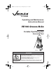
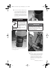
TM-VE106 3736 Rev_B.fm Page 20 Monday, May 9, 2005 12:02 PM 5. Using a punch and hammer (these tools are not furnished), tap the lower roll/main shaft out from the rear of the tool, as shown above. 3. Remove the drive key from the rear of the shaft. 6. Pull the lower roll/main shaft out from the front of the tool head. Using a soft cloth, remove any debris and excess grease from the lower roll/main shaft. 4.
TM-VE106 3736 Rev_B.fm Page 21 Monday, May 9, 2005 12:02 PM UPPER ROLL REMOVAL The same upper roll is used for standard grooving of carbon steel pipe and stainless steel pipe. When preparing to groove copper tubing or “ES” grooves, the upper roll for carbon steel/ stainless steel pipe must be removed and the appropriate roll must be installed. 4. Follow the “Upper Roll Installation” section shown below. UPPER ROLL INSTALLATION 1. Select the proper upper roll for the pipe size and material to be grooved.
TM-VE106 3736 Rev_B.fm Page 22 Monday, May 9, 2005 12:02 PM LOWER ROLL/MAIN SHAFT INSTALLATION 1. Select the proper lower roll/main shaft for the pipe size and material to be grooved. Refer to the "Tool Rating and Roll Selection" section on page 28. NOTICE • Upper roll installation must be complete prior to proceeding with lower roll/main shaft installation. 4. Install the lower roll/main shaft into the tool head.
TM-VE106 3736 Rev_B.fm Page 23 Monday, May 9, 2005 12:02 PM LUBRICATION 6. Install the lock washer, and tighten the 3/ -inch hex bolt to retain the drive key. 8 MAINTENANCE DANGER • Before performing any maintenance on the tool, disconnect the power cord from the electrical source. Failure to follow this instruction could result in death or serious personal injury. This section provides information about keeping tools in proper operating condition and guidance for making repairs, when necessary.
TM-VE106 3736 Rev_B.fm Page 24 Monday, May 9, 2005 12:02 PM 2. Apply grease underneath the toggle pad. 4. Apply grease to the locations where the roll arm slides against the tool body. 5. After every 8 hours of operation, apply grease to the grease fitting of the upper roll shaft. 3. Apply grease to the ball-and-socket joint of the toggle pad.
TM-VE106 3736 Rev_B.fm Page 25 Monday, May 9, 2005 12:02 PM PARTS ORDERING INFORMATION VAPS224 VICTAULIC ADJUSTABLE PIPE STAND When ordering parts, the following information is required for the Victaulic Tool Company to process the order and send the correct part(s). Request the RP-VE106 Repair Parts List for detailed drawings and parts listings. 1. Tool Model Number – VE106 2. Tool Serial Number – The serial number is stamped onto the tool body 3.
TM-VE106 3736 Rev_B.fm Page 26 Monday, May 9, 2005 12:02 PM TROUBLESHOOTING Problem Possible Cause Pipe/tubing will not Incorrect pipe/tubing stay in grooving rolls. positioning of long pipe/tubing length. Solution Refer to the "Long Pipe/Tubing Lengths" section on page 11. Lower roll/main shaft and pipe/ Turn the drive motor switch to the opposite tubing are not rotating rotation position. counterclockwise. Pipe/tubing stops rotating during grooving.
TM-VE106 3736 Rev_B.fm Page 27 Monday, May 9, 2005 12:02 PM Shear pin broke. Pipe/tubing grooves do not meet Victaulic specifications. The “A” Gasket Seat or “B” Groove Width dimensions do not meet Victaulic specifications. Rolls were being fed too fast. Replace the shear pin, and groove the pipe/tubing at a slower rate. Pipe/tubing is beyond the wall thickness capacity of the tool, or the pipe/tubing material is too hard.
TM-VE106 3736 Rev_B.fm Page 28 Monday, May 9, 2005 12:02 PM TOOL RATING AND ROLL SELECTION STANDARD AND “ES” ROLLS FOR STEEL PIPE – COLOR-CODED BLACK Pipe Size Actual Outside Nominal Diameter Size inches inches (mm) 11/4 1 1 /2 2 1 2 /2 3 4 41/2 5 6 Dimensions – inches/millimeters Steel Pipe Wall Thickness * Minimum Maximum 1.660 0.065 0.140 42,4 1,7 3,6 1.900 0.065 0.145 48,3 1,7 3,7 2.375 0.065 0.154 60,0 1,7 3,9 2.875 0.083 0.203 73,0 2,1 5,2 3.500 0.083 0.
TM-VE106 3736 Rev_B.fm Page 29 Monday, May 9, 2005 12:02 PM ROLLS FOR CTS US STANDARD – ASTM DRAWN COPPER TUBING – COLOR-CODED COPPER Tube Size Nominal Size inches Actual Outside Diameter inches (mm) 2 21/2 3 4 5 6 Dimensions – inches/millimeters Copper Tubing Wall Thickness * Minimum Maximum 2.125 0.042 0.083 54,0 1,1 2,1 2.625 0.065 0.095 66,7 1,7 2,4 3.125 0.045 0.109 79,4 1,1 2,8 4.125 0.058 0.134 104,8 1,5 3,4 5.125 0.072 0.160 130,2 1,8 4,1 6.125 0.083 0.
TM-VE106 3736 Rev_B.fm Page 30 Monday, May 9, 2005 12:02 PM EXPLANATION OF CRITICAL ROLL GROOVE DIMENSIONS B A B OD T C D Exaggerated for clarity Standard Roll Groove Outside Diameter (“OD”) Dimension – The outside diameter of roll grooved pipe must not vary from the specifications listed in the following tables. The maximum allowable tolerance from square-cut pipe ends is 0.030 inch (0,8 mm) for 11/4 - 3-inch sizes and 0.045 inch (1,1 mm) for 4 – 6-inch sizes.
VE106 Groove-N-Go Tool 159,0 mm 152,4 mm 5 139,7 mm 133,0 mm 41/2 4 108,0 mm 3 76,1 mm 2 /2 1 2 11/2 11/4 5.050 128,3 5.303 134,7 5.556 141,1 5.619 142,7 6.056 153,8 6.313 160,4 5.000 127,0 5.250 133,0 5.500 139,7 5.563 141,3 6.000 152,4 6.250 159,0 107,2 115,4 88,1 4.219 89,8 4.293 88,9 4.250 114,3 75,4 3.469 77,0 3.535 76,1 3.500 109,0 72,3 2.970 73,8 3.030 73,0 3.000 4.545 59,7 2.846 60,9 2.904 60,3 2.875 108,0 47,8 2.351 48,7 2.
32 6.563 166,7 6.688 169,9 6.500 165,1 6.625 168,3 167,5 6.594 164,3 6.469 Pipe Outside Diameter Max. Min. 15,9 0.625 15,9 0.625 16,7 0.656 16,7 0.656 15,1 0.594 15,1 0.594 8,7 0.344 8,7 0.344 9,5 0.375 9,5 0.375 8,0 0.313 8,0 0.313 Dimensions – inches (millimeters) Gasket Seat “A” Groove Width “B” Basic Max. Min. Basic Max. Min. 164,0 6.455 160,8 6.330 163,4 6.433 160,2 6.308 Groove Diameter “C” Max. Min. 2,2 0.085 2,2 0.085 Groove Depth “D” (Ref.
VE106 Groove-N-Go Tool 206,4 206,4 206,3 8.121 155,5 6.123 130,1 5.123 104,7 4.123 79,3 3.123 66,6 2.623 53,9 2.123 Basic 15,5 0.610 15,5 0.610 15,5 0.610 15,5 0.610 15,5 0.610 15,5 0.610 15,5 0.610 16,3 0.640 16,3 0.640 16,3 0.640 16,3 0.640 16,3 0.640 16,3 0.640 16,3 0.640 Gasket Seat “A” Max. Min. 14,7 0.580 14,7 0.580 14,7 0.580 14,7 0.580 14,7 0.580 14,7 0.580 14,7 0.580 8,4 0.330 8,4 0.330 8,4 0.330 8,4 0.330 8,4 0.330 8,4 0.
TM-VE106 3736 Rev_B.fm Page 34 Monday, May 9, 2005 12:02 PM Facilities Locations VICTAULIC GLOBAL LOCATIONS VICTAULIC TOOL COMPANY WORLD HEADQUARTERS UNITED STATES CENTRAL AND SOUTH AMERICA P.O. Box 31 Easton, PA 18044-0031 1-610-559-3300 1-610-923-3090 (fax) victools@victaulic.com P. O. Box 31 Easton, PA USA 18044-0031 P.O. Box 31 Easton, PA 18044-0031 1-610-559-3300 1-610-250-8817 (fax) victaulic@victaulic.com P.O.