
Specifications
42
was chosen because the designers already had experience using it and no extra expenses
would be necessary to acquire th e tool suite necessary to develop with this processor.
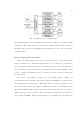
The s election of the MSP430F14X [41] does have two drawbacks. First, the code size
is limited to 60K bytes. The data manager application is moderately complex, but the
engineering team estimated th at this application will not exceed 60K bytes. Second, the
largest chip size available is 64 pins. This does not directly satisfy the I/O requirements.
Therefore, all control signals must be routed though multiple latching octal-line drivers.
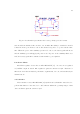
4.1.3 SDI-12 Communications
The SDI-12 specifications r equ ir e a 12V power line, a 5V bidirectional digital commu-
nication line, and a ground line. The power line comes directly from the SEPIC switcher
through a power switch. The SDI-12 protocol specifies usin g an asynchronous 1200 baud
signal with seven data bits, even parity, and one stop bit in a byte packet. The selected
MCU does not have a spare UART to run this communication sequence. Therefore, the
message passing will be done using a timer assisted capture/compare port (CCP). This
port set a logic output or sampled a logic input based on a 1200 baud time. The only other
element to consider is that the MCU ports operate on 3.3V and the SDI-12 line needs to
operate at 5V. To rectify this discrepancy, the SN74LVC1T45 [42] is a 1-bit, dual-supply,
bidirectional line driver was used to step up or step down the line voltage. Over voltage
protection was also included.
4.1.4 Analog Measurements
The analog ports were implemented using the MCU’s internal ADC and references as
well as other external parts. The physical terminal comes with power, ground, and signal
connectors. The power connector receives its power from directly f rom the SEPIC switcher
through a power switch. The signal port is protected from over-voltage and reverse-voltage
using a zener diode. The signal then passes through a conditioning circuit. This circuit
can be configured to interpret the incoming signal as a 0-20mA current loop signal or as a
voltage signal. If it is a voltage signal, the signal will be processed with hardware to range