ILLUSTRATED PARTS MANUALS T300 THERMAL BINDER 220-240V T300 THERMAL BINDER 220-240V ILLUSTRATED PARTS LISTS AND SERVICE INSTRUCTIONS Compiled by Approved by Issue No 2 (Technical Manager) Date REXEL BUSINESS MACHINES, DROITWICH, WORCESTERSHIRE, WR9 9AP, ENGLAND TELEPHONE +44 (0) 1905 771555 FAX +44 (0) 1905 823374 T300.
ILLUSTRATED PARTS MANUALS T300 THERMAL BINDER 220-240V TABLE OF CONTENTS ILLUSTRATED PARTS MANUAL T300 THERMAL BINDER 220-240V Contents Page 2 Preface Page 3 Illustrated parts list - Mouldings Mechanism and Electrics Pages 4 – 5 Pages 6 – 8 Service Instructions - To serial No A545817 Pages 9 – 14 Section 1.0 Replacement of Top Cover Section 2.0 Replace lid moulding Section 2.1 Replacement of Heater Assembly Section 2.2 Replacement of Fixing Blocks Section 2.3 Replacement of Insulation Section 2.
ILLUSTRATED PARTS MANUALS T300 THERMAL BINDER 220-240V PREFACE SERVICE PREPARATION This manual provides the instructions for the replacement of all the components that may become worn or damaged. Details of replacement parts and ordering information are given in associated illustrated parts list. Illustrated Parts Lists For each machine give full details of the replacement part numbers with supporting diagrams to show the location of the components.
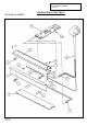
ILLUSTRATED PARTS MANUALS T300 THERMAL BINDER 220-240V MOULDINGS No 1 2 3 4 5 6 7 8 9 10 11 12 13 Description Service Call Decal Bottom Moulding On Button – Grey Off Button – Red Programme Select Button – Yellow Bind Button – Green Lid Pad Print Top Cover Pad Print No 4 x ½” Pan Plasfast Screw Self Adhesive Rubber Feet Document Feet Spring Arm Coil Spring T300.
ILLUSTRATED PARTS MANUALS T300 THERMAL BINDER 220-240V MOULDINGS T300.
ILLUSTRATED PARTS MANUALS T300 THERMAL BINDER 220-240V MECHANISM & ELECTRICS N o 1 2 Description Part Qty Comments Heater Assembly 230V 600W Heater Assembly 230V 600W Heater Extrusion Heater Extrusion A52505 A52527 D52503 1 1 1 To Serial No A545817 From Serial No A545818 To Serial No A545817 From Serial No A545818 Inc in A52527 3 4 5 6 7 Heater Fixing Block D52504 2 Compression Spring (clip) Thermal Fuse Holder (Clip) Thermal Fuse Holder (Clip) D52511 D52513 3 4 To Serial No A545817 From Ser
ILLUSTRATED PARTS MANUALS T300 THERMAL BINDER 220-240V MECHANSIM & ELECTRICS To Serial No A545817 T300.
ILLUSTRATED PARTS MANUALS T300 THERMAL BINDER 220-240V MECHANSIM & ELECTRICS From Serial No A545818 T300.
ILLUSTRATED PARTS MANUALS T300 THERMAL BINDER 220-240V SERVICE INSTRUCTIONS This manual provides instructions for the replacement of components that may become worn or damaged. WARNING Check rating plate details are compatible with electric supply. Disconnect mains supply before removing cover. SECTION 1.0 (To serial no A545817) Replacement of Top Cover 1. Ensure that mains cable is disconnected from the supply. 2.
ILLUSTRATED PARTS MANUALS T300 THERMAL BINDER 220-240V SECTION 2.0 (To serial no A545817) Replace Lid Moulding 1. Remove lid from top cover, by bowing inwards to release hinge pins. 2. Replace lid. 3. Check that pivot pins are correctly aligned in top cover. 4. Check lid opens and closes correctly. SECTION 2.1 a. Replacement of Heater Assembly 1. Carry out procedures 1 to 4 in section 1.0. 2. The heater assembly is secured to 2 off heater fixing blocks by four fixing screws. 3.
ILLUSTRATED PARTS MANUALS T300 THERMAL BINDER 220-240V SECTION 2.2 Replacement of Fixing Blocks 1. Carry out procedures 1 to 4 section 2.1 2. Turn base moulding upside down. 3. Remove service decal and rating plate. 4. Unscrew four fixing screws 5. Blocks can now be replaced 6. Reassemble machine in reverse sequence of operations 1 to 4. SECTION 2.3 Replacement of insulation 1. Carry out procedures 1 to 4 section 2.1 2. Insulation is secured using double sided sticky tape. 3.
ILLUSTRATED PARTS MANUALS T300 THERMAL BINDER 220-240V SECTION 3.0 Replacement of PCB 1. Carry out procedures 1 to 7 section 1. 2. Replace the PCB 3. Reassemble machine In reverse sequence. SECTION 4.0 Replacement of document support bar/spring/lever arm 1. Carry out procedures 1 to 4 section 1. 2. To remove extension spring unhook from rear screw boss and lever arm. 3. Replace spring. 4. To remove lever arm carry out procedures 1 to 4 section 1, and then 9 to 11 section 1. 5.
ILLUSTRATED PARTS MANUALS T300 THERMAL BINDER 220-240V Replacement of Thermistor 1. Carry out procedures 1 to 4 section 2.1 2. Remove thermistor for connection on PCB. 3. The PCB may be removed to ease replacement. If required refer to section 1 produce 6. 4. Replace thermistor 5. Reverse assembly of operations 3 to 1 if PCB was removed, otherwise 2 to 1. T300.
ILLUSTRATED PARTS MANUALS T300 THERMAL BINDER 220-240V Section 5.0 WIRING DIAGRAM 220/240V WD317 TO SERIAL NO A545817 T300.
ILLUSTRATED PARTS MANUALS T300 THERMAL BINDER 220-240V SERVICE INSTRUCTIONS This manual provides instructions for the replacement of components that may become worn or damaged. WARNING Check rating plate details are compatible with electric supply. Disconnect mains supply before removing cover. SECTION 6.0 (From serial no A545818) Replacement of Top Cover 17. Ensure that mains cable is disconnected from the supply. 18.
ILLUSTRATED PARTS MANUALS T300 THERMAL BINDER 220-240V SECTION 7.0 (From serial no A545818) Replace Lid Moulding 5. Remove lid from top cover, by bowing inwards to release hinge pins. 6. Replace lid. 7. Check that pivot pins are correctly aligned in top cover. 8. Check lid opens and closes correctly. SECTION 7.1 a. Replacement of Heater Assembly (including Thermistor) 1. Carry out procedures 1 to 4 in section 6.0. 2.
ILLUSTRATED PARTS MANUALS T300 THERMAL BINDER 220-240V SECTION 7.3 Replacement of insulation 6. Carry out procedures 1 to 4 section 7.1 7. Insulation is secured using double sided sticky tape. 8. Ease free sticky tape from insulation. 9. Remove and replace insulation. 10. Reassemble machine in reverse sequence of operations 1 to 3. SECTION 7.4 Replacement of Base Moulding 7. Carry out procedures 1 to 5 section 7.1 8. The extrusion/heater assembly will now become free. 9. Place on one side.
ILLUSTRATED PARTS MANUALS T300 THERMAL BINDER 220-240V SECTION 9.0 Replacement of document support bar/spring/lever arm 8. Carry out procedures 1 to 4 section 6. 9. To remove extension spring unhook from rear screw boss and lever arm. 10. Replace spring. 11. To remove lever arm carry out procedures 1 to 4 section 6, and then 9 to 11 section 6. 12. To remove document support bar, carry out procedures 1 to 5 section 6.0 and procedures 9 to 14 in section 6.0. 13. Replace document support bar. 14.
ILLUSTRATED PARTS MANUALS T300 THERMAL BINDER 220-240V WIRING DIAGRAM 220/240V WD404 T300.
ILLUSTRATED PARTS MANUALS T300 THERMAL BINDER 220-240V SECTION 11.0 SPECIFICATION SHEET T300 POWER SUPPLY 220/240V 50Hz HEIGHT 95 mm WIDTH 370 mm DEPTH 220 mm WEIGHT 2 Kgs MACHINE POWER 600W DOCUMENT SIZE MAX A4 T300.
ILLUSTRATED PARTS MANUALS T300 THERMAL BINDER 220-240V AMENDMENT RECORD SHEET ISSUE DECRIPTION NO 1 2 T300.doc Issue No 1 CARO No Original Instructions altered to include double insulated product.