CONFIGURING THE BARRICADE Status 4-50
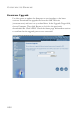
ADSL Parameter Description Status Line Status Shows the current status of the ADSL line. Data Rate Upstream Maximum data rate upstream. Downstream Maximum data rate downstream. Operation Data/Defect Indication Noise Margin Upstream Minimum noise margin upstream. Downstream Minimum noise margin downstream. Output Power Maximum fluctuation in the output power. Attenuation Upstream Maximum reduction in the strength of the upstream signal.
CONFIGURING THE BARRICADE Parameter Description Loss of Power Defect Failures due to loss of power. Fast Path HEC Error Fast Path Header Error Concealment errors. Interleaved Path HEC Error Interleaved Path Header Error Concealment errors. Statistics (Superframes represent the highest level of data presentation. Each superframe contains regular ADSL frames, one of which is used to provide superframe synchronization, identifying the start of a superframe.
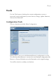
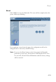
TOOLS Tools Use the Tools menu to backup the current configuration, restore a previously saved configuration, restore factory settings, update firmware, and reset the Barricade. Configuration Tools Choose a function and click More Configuration. Backup allows you to save the Barricade Router’s configuration to a file. You can then check Restore to restore the saved backup configuration file. Restore to Factory Defaults resets the Barricade to the original settings.
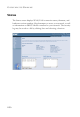
CONFIGURING THE BARRICADE Firmware Upgrade Use this screen to update the firmware or user interface to the latest versions. Download the upgrade file from the SMC Web site (www.smc.com) and save it to your hard drive. In the Upgrade Target field, choose Firmware. Then click Browse to look for the previously downloaded file. Click APPLY. Check the Status page Information section to confirm that the upgrade process was successful.
TOOLS Reset Click APPLY to reset the Barricade. The reset will be complete when the power LED stops blinking. If you perform a reset from this page, the configurations will not be changed back to the factory default settings. Note: If you use the Reset button on the front panel, the Barricade performs a power reset. If the button is held depressed for over five seconds, all the LEDs will illuminate and the factory settings will be restored.
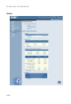
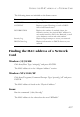
CONFIGURING THE BARRICADE Status The Status screen displays WAN/LAN connection status, firmware, and hardware version numbers, illegal attempts to access your network, as well as information on DHCP clients connected to your network. The security log may be saved to a file by clicking Save and choosing a location.
FINDING THE MAC ADDRESS OF A NETWORK CARD The following items are included on the Status screen: Parameter Description INTERNET Displays WAN connection type and status. GATEWAY Displays system IP settings, as well as DHCP Server and Firewall status. INFORMATION Displays the number of attached clients, the firmware versions, the physical MAC address for each media interface, and for the Barricade, as well as the hardware version and serial number.
CONFIGURING THE BARRICADE 4-58
CHAPTER 5 CONFIGURING PRINTER SERVICES To use the print server built into the Barricade, you must first install the Port Monitor program as described in the following section for Windows 95/98/Me. To set up the Barricade Print Server for Windows NT, see “Printer Server Setup in Windows NT” on page 5-4. For Windows 2000, see “Printer Server Setup in Windows 2000” on page 5-6. For Windows XP, see “Printer Server Setup in Windows XP” on page 5-8.
CONFIGURING PRINTER SERVICES 2. The next screen indicates that the print client uses the TCP/IP network protocol to monitor print requests. Click Next. 3. Select the destination folder and click on the Next button. The setup program will then begin to install the programs into the destination folder.
PRINTER SERVER SETUP IN WINDOWS 95/98/ME 4. Select the Program Folder that will contain the program icon for uninstalling the port monitor, and then click Next. 5. Enter the printer port name that will be used to identify the port monitor in your system, and click Next. 6. When the setup program finishes installing the port monitor, choose “Yes, I want to restart my computer now” and then click OK.
CONFIGURING PRINTER SERVICES Printer Server Setup in Windows NT 1. On a Windows NT platform, open the Printers window in the My Computer menu, and double-click the Add Printer icon. 2. Follow the prompts to add a local printer to your system.
PRINTER SERVER SETUP IN WINDOWS NT 3. Select the monitored port. The default port name is “SMC100.” Then click the Configure Port button. 4. Enter the IP address of the Barricade and click OK. Click Next in the Add Printer Wizard dialog box. 5. Specify the printer type attached to the Barricade. 6. Continue following the prompts to complete the installation of the Barricade print server. The printer type you specified will now be added to your Printers menu.
CONFIGURING PRINTER SERVICES Printer Server Setup in Windows 2000 1. On your desktop, click Start/Settings/Printers to open the Printers window, then double-click the Add Printer icon. 2. Follow the prompts to add a local printer to your system. 3. Specify the printer type attached to the Barricade.
PRINTER SERVER SETUP IN WINDOWS 2000 4. Select the monitored port. The default port name is “SMC100.” Click the Configure Port button. 5. Enter the IP address of the Barricade and click OK. Then click Next in the Add Printer Wizard dialog box. 6. Continue following the prompts to complete the installation of the Barricade print server. The printer will now be added to your Printers menu.
CONFIGURING PRINTER SERVICES Printer Server Setup in Windows XP 1. On your desktop, click Start/Printers and Faxes. 2. The Printers and Faxes dialog box will open. You should see a menu with options on the left-hand side on the screen. Click Add a Printer to launch the Add Printer Wizard.
PRINTER SERVER SETUP IN WINDOWS XP 3. Click Next. 4. Select “Local printer attached to this computer” and uncheck the “Automatically detect and install my Plug and Play printer” option. Click Next.
CONFIGURING PRINTER SERVICES 5. Select “Create a new port:” and then choose “Standard TCP/IP Port” on Type of port: drop-down list. Click Next. 6. The Add Standard TCP/IP Printer Port Wizard window will open. Click Next.
PRINTER SERVER SETUP IN WINDOWS XP 7. Provide the appropriate IP and Port name for your new printer port on this window, then click Next. Please set the same IP address on the Printer Port and the router (for example: 192.168.2.1). In the Port Name field, choose whatever you like. For simplicity we have chosen “IP_192.168.2.1” to maintain consistency with the default IP settings of the Barricade. 8. Select the Custom radio button and click Settings.
CONFIGURING PRINTER SERVICES 9. The Configure Standard TCP/IP Port Monitor window will open. Under Protocol category, select LPR. Then, set the Queue Name as “LPT1” under LPR Settings category, and uncheck the LPR Byte Counting Enabled checkbox. Click OK. 10. This should take you back to the Add Standard TCP/IP Printer Port Wizard window. Click Next.
PRINTER SERVER SETUP IN WINDOWS XP 11. Click Finish to complete the configuration of TCP/IP port. 12. After configuration, continue to install a printer. In the Add Printer Wizard window as shown below, choose your printer on Manufacturer and Printers list. Click Next. Note: If your printer is not listed here, refer to your printer documentation for installation instruction.
CONFIGURING PRINTER SERVICES 13. Type a name for your printer. Click Next. 14. Select “Do not share this printer,” then click Next.
PRINTER SERVER SETUP IN WINDOWS XP 15. You will need to confirm some information before you successfully test your printer. When prompt to print a test page request, choose No. Click Next. 16. You should see all your printer information on this screen. Click Finish to complete the installation.
CONFIGURING PRINTER SERVICES 17. Now you need to configure some properties on your printer. Click Start/Printers and Faxes on your desktop. On the Printer and Faxes window, select the printer you just installed, right-click the mouse and click Properties. 18. The Printer Properties window will open as shown below.
PRINTER SERVER SETUP IN WINDOWS XP 19. Follow the instructions below to verify that your printer is configured properly: • Click the Advanced tab. Select “Spool printer documents so program finishes printing faster” and select “Start printing after last page is spooled.” Then check both “Print spooled documents first” and “Enable advanced printing features” checkboxes.
CONFIGURING PRINTER SERVICES • Click the Ports tab. Verify that the selected TCP/IP port is the one you just created. Click Apply to save the settings. • Click the General tab. Click Print Test Page to verify that you have successfully setup your LPR printing port on Windows XP. Now you can print through the SMC Barricade Router. Printer Server Setup in Unix Systems Follow the standard configuration procedure on your Unix platform to set up the Barricade print server. The printer name is “lpt1.
CHAPTER A TROUBLESHOOTING This section describes common problems you may encounter and possible solutions to them. The Barricade can be easily monitored through panel indicators to identify problems. Troubleshooting Chart Symptom Action LED Indicators Power LED is Off • Check connections between the Barricade, the external power supply, and the wall outlet.
TROUBLESHOOTING Troubleshooting Chart Symptom Action LED Indicators Link LED is Off • Verify that the Barricade and attached device are powered on. • Be sure the cable is plugged into both the Barricade and the corresponding device. • Verify that the proper cable type is used and that its length does not exceed the specified limits. • Be sure that the network interface on the attached device is configured for the proper communication speed and duplex mode.
TROUBLESHOOTING Troubleshooting Chart Symptom Action Management Problems Cannot connect using the Web browser Forgot or lost the password • Be sure to have configured the Barricade with a valid IP address, subnet mask, and default gateway. • Check that you have a valid network connection to the Barricade and that the port you are using has not been disabled. • Check the network cabling between the management station and the Barricade.
TROUBLESHOOTING Troubleshooting Chart Symptom Action Wireless Problems A wireless PC cannot associate with the Barricade. • Make sure the wireless PC has the same SSID settings as the Barricade. See “Channel and SSID” on page 4-26. • You need to have the same security settings on the clients and the Barricade. See “Encryption” on page 4-28. The wireless network is often interrupted. • Move your wireless PC closer to the Barricade to find a better signal.
APPENDIX B CABLES Ethernet Cable Caution: DO NOT plug a phone jack connector into any RJ-45 port. Use only twisted-pair cables with RJ-45 connectors that conform with FCC standards. Specifications Cable Types and Specifications Cable Type Max. Length Connector 10BASE-T Cat. 3, 4, 5 100-ohm UTP 100 m (328 ft) RJ-45 100 m (328 ft) RJ-45 100BASE-TX Cat. 5 100-ohm UTP Wiring Conventions For Ethernet connections, a twisted-pair cable must have two pairs of wires.
CABLES Each wire pair must be attached to the RJ-45 connectors in a specific orientation. The following figure illustrates how the pins on an Ethernet RJ-45 connector are numbered. Be sure to hold the connectors in the same orientation when attaching the wires to the pins. Figure B-1. RJ-45 Ethernet Connector Pin Numbers RJ-45 Port Connection Use the straight-through CAT -5 Ethernet cable provided in the package to connect the Barricade to your PC.
ETHERNET CABLE Pin Assignments With 100BASE-TX/10BASE-T cable, pins 1 and 2 are used for transmitting data, and pins 3 and 6 for receiving data. RJ-45 Pin Assignments Pin Number Assignment1 1 Tx+ 2 Tx- 3 Rx+ 6 Rx- 1: The “+” and “-” signs represent the polarity of the wires that make up each wire pair. Straight-Through Wiring If the port on the attached device has internal crossover wiring (MDI-X), then use straight-through cable.
CABLES Crossover Wiring If the port on the attached device has straight-through wiring (MDI), use crossover cable.
ADSL CABLE ADSL Cable Use standard telephone cable to connect the RJ-11 telephone wall outlet to the RJ-11 ADSL port on the ADSL Router. Caution: Do not plug a phone jack connector into an RJ-45 port. Specifications Cable Types and Specifications Cable Type Connector ADSL Line Standard Telephone Cable RJ-11 For ADSL connections, a cable requires one pair of wires. Each wire is identified by different colors. For example, one wire might be red and the other, red with white stripes.
Blue/White White/Blue White/Orange Blue/White White/Blue Orange/White Black Red Green Yellow CABLES R1 T1 T2 R1 T1 R2 T2 R1 T1 R2 123456 123456 123456 6x2 Jack 6x4 Jack 6x4 Jack T = Tip R = Ring Pin Signal Name 1 Not used 2 Line 2 Tip Black or White/Orange 3 Line 1 Ring Red or Blue/White 4 Line 1 Tip Green or White/Blue 5 Line 2 Ring Yellow or Orange/White 6 Not used Figure B-3.
APPENDIX C SPECIFICATIONS Standards Compliance CE Mark Emissions FCC Class B, VCCI Class B Industry Canada Class B EN55022 (CISPR 22) Class B C-Tick - AS/NZS 3548 (1995) Class B Immunity EN 61000-3-2/3 EN 61000-4-2/3/4/5/6/8/11 Safety UL 1950 EN60950 (TÜV) CSA 22.2 No. 950 IEEE 802.3 10 BASE-T Ethernet IEEE 802.3u 100 BASE-TX Fast Ethernet IEEE 802.11b Wireless LAN Modem Standards ITU G.992.1 (G.dmt) ITU G.992.2 (G.Lite) ITU G.994.1 (G.handshake) ITU T.
SPECIFICATIONS WAN Interface 1 ADSL RJ-11 port Indicator Panel Power, Ethernet, ADSL Syn, ADSL Data Dimensions 220 x 132.8 x 30.5 mm (8.66 x 5.23 x 1.20 in) Weight 0.6 kg (1.32 lbs) Input Power 12 V 1 A Power Consumption 12 Watts max.
GLOSSARY 10BASE-T IEEE 802.3 specification for 10 Mbps Ethernet over two pairs of Category 3, 4, or 5 UTP cable. 100BASE-TX IEEE 802.3u specification for 100 Mbps Fast Ethernet over two pairs of Category 5 UTP cable. Access Point (AP) An interface between the wireless network and a wired network. Access points combined with a distribution system (e.g. Ethernet) support the creation of multiple radio cells (BSSs) that enable roaming throughout a facility.
GLOSSARY Bandwidth The difference between the highest and lowest frequencies available for network signals. Also synonymous with wire speed, the actual speed of the data transmission along the cable. Basic Service Set (BSS) A set of 802.11-compliant stations that operate as a fully-connected wireless network.
GLOSSARY Ethernet A network communication system developed and standardized by DEC, Intel, and Xerox, using baseband transmission, CSMA/CD access, logical bus topology, and coaxial cable. The successor IEEE 802.3 standard provides for integration into the OSI model and extends the physical layer and media with repeaters and implementations that operate on fiber, thin coax and twisted-pair cable. File Transfer Protocol (FTP) A TCP/IP protocol for file transfer.
GLOSSARY IEEE 802.11 Specifies medium access and physical layer specifications for 1 Mbps and 2 Mbps wireless connectivity within a local area. IEEE 802.3x Defines Ethernet frame start/stop requests and timers used for flow control on full-duplex links. International Control Message Protocol (ICMP) Network layer Internet protocol that reports errors and provides other information relevant to IP packet processing. Documented in RFC 792.
GLOSSARY Node Any network-addressable device on the network, such as a router or network interface card. Point-to-Point Protocol (PPP) A protocol that provides router-to-router and host-to-network connections over both synchronous and asynchronous circuits. PPP is the successor to SLIP. RJ-45 Connector A connector for twisted-pair wiring. Routing Information Protocol (RIP) A common type of routing protocol. RIP bases its routing path on the distance (number of hops) to the destination.
GLOSSARY Transmission Control Protocol (TCP) A commonly used protocol for establishing and maintaining communications between applications on different computers. TCP provides full-duplex, acknowledged, and flow-controlled service to upper-layer protocols and applications. User Data Protocol (UDP) A connectionless protocol that works at the OSI transport layer. UDP transports datagrams but does not acknowledge their receipt. UTP Unshielded twisted-pair cable.
FOR TECHNICAL SUPPORT, CALL: From U.S.A. and Canada (24 hours a day, 7 days a week) (800) SMC-4-YOU; (949) 679-8000; Fax: (949) 679-1481 From Europe (8:00 AM - 5:30 PM UK Time) 44 (0) 118 974 8700; Fax: 44 (0) 118 974 8701 INTERNET E-mail addresses: techsupport@smc.com european.techsupport@smc-europe.com support@smc-asia.com Driver updates: http://www.smc.com/index.cfm?action=tech_support_drivers_downloads World Wide Web: http://www.smc.com http://www.smc-europe.com http://www.smc-asia.