CAP2315A 802.
Installation Guide Guide 802.11b/g AP Cradle IEEE 802.
CAP2315A E072006-EK-R01 150xxxxxxxxxxxx
Compliances Federal Communication Commission Interference Statement This equipment has been tested and found to comply with the limits for a Class B digital device, pursuant to Part 15 of the FCC Rules. These limits are designed to provide reasonable protection against harmful interference in a residential installation.
EC Conformance Declaration Marking by the above symbol indicates compliance with the Essential Requirements of the R&TTE Directive of the European Union (1999/5/EC). This equipment meets the following conformance standards: • • • • EN 60950-1 (IEC 60950-1) - Product Safety EN 300 328 - Technical requirements for 2.
Contents Chapter 1: Introduction 1-1 Package Checklist Hardware Description Wi-Fi Phone Cradle LED Indicators Ethernet Port Reset Button Power Connector 1-1 1-2 1-3 1-3 1-3 1-4 1-4 Chapter 2: Hardware Installation 2-1 Access Point Configuration 2-2 Appendix A: Troubleshooting A-1 Diagnosing Access Point Indicators Appendix B: Cables and Pinouts Twisted-Pair Cable Assignments 10/100BASE-TX Pin Assignments Straight-Through Wiring Crossover Wiring Appendix C: Specifications A-1 B-1 B-1 B-1 B-2 B-2 C
Contents iv
Chapter 1: Introduction The Cradle Access Point is an IEEE 802.11b/g (Wi-Fi) access point that provides a quality wireless Voice over Internet Protocol (VoIP) service for Wi-Fi phones, and high-speed data communications between a wired LAN and other 802.11b/g mobile devices. The access point also includes a cradle for charging a Wi-Fi phone. The access point software provides two “virtual” wireless interfaces that separate the Wi-Fi Phone traffic from the regular data traffic.
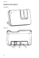
Introduction Hardware Description Front Panel WLAN LAN Back Panel Ethernet LAN RJ-45 Port 1-2 Power Socket Reset Button
Hardware Description Wi-Fi Phone Cradle The access point accepts a Wi-Fi Phone in its cradle for charging the battery. When the access point is powered on, just place the phone in the cradle and charging starts immediately. LED Indicators The access point includes three status LED indicators, as described in the following figure and table. WLAN Power LAN 802.11g Wireless Link/Activity Ethernet Link/Activity LED Status PWR/SEATED On Green Indicates that the system is working normally.
Introduction Reset Button The Reset button is used to restart the access point or restore the factory default configuration. If you hold down the button for less than 5 seconds, the access point will perform a hardware reset. If you hold down the button for 5 seconds or more, any configuration changes you may have made are removed, and the factory default configuration is restored to the access point. Power Connector The access point does not have a power switch.
Chapter 2: Hardware Installation To install the Cradle Access Point, follow these steps: 1. Select a Site – Choose a proper place for the access point. In general, the best location is at the center of your wireless coverage area, within line of sight of all wireless devices. For optimum performance, consider these points: • Mount the access point as high as possible above any obstructions in the coverage area.
Hardware Installation Access Point Configuration The access point can be configured by connecting a PC to its Ethernet port and accessing the web interface. The default IP address of the access point is 192.168.1.20, with login user name “admin” and no default password. For information on configuring the access point, refer to the Management Guide.
Appendix A: Troubleshooting Diagnosing Access Point Indicators Troubleshooting Chart Symptom Action PWR/SEATED LED is Off • AC power adapter may be disconnected. Check connections between the access point, the power adapter, and the wall outlet. LAN LED is Off • Verify that the access point and attached device are powered on. • Be sure the cable is plugged into both the access point and corresponding device. • Verify that the proper cable type is used and its length does not exceed specified limits.
Troubleshooting A-2
Appendix B: Cables and Pinouts Twisted-Pair Cable Assignments For 10/100BASE-TX connections, a twisted-pair cable must have two pairs of wires. Each wire pair is identified by two different colors. For example, one wire might be green and the other, green with white stripes. Also, an RJ-45 connector must be attached to both ends of the cable. Caution: Each wire pair must be attached to the RJ-45 connectors in a specific orientation.
Cables and Pinouts Straight-Through Wiring If the twisted-pair cable is to join two ports and only one of the ports has an internal crossover (MDI-X), the two pairs of wires must be straight-through.
Appendix C: Specifications Maximum Channels FCC/IC: 1-11 ETSI: 1-13 France: 10-13 MKK: 1-14 Taiwan: 1-11 Maximum Clients 32 per VAP interface Data Rate 802.11g: 6, 9, 11, 12, 18, 24, 36, 48, 54 Mbps per channel 802.11b: 1, 2, 5.5, 11 Mbps per channel Modulation Type 802.11g: CCK, BPSK, QPSK, OFDM 802.11b: CCK, BPSK, QPSK Network Configuration Infrastructure Operating Frequency 2.4 ~ 2.4835 GHz (US, Canada, ETSI) 2.4 ~ 2.497 GHz (Japan) 2.400 ~ 2.4835 GHz (Taiwan) Wireless Output Power 802.
Specifications Weight 300 g (10.6 oz) LED Indicators PWR/SEATED (Power), LAN (Ethernet Link/Activity), WLAN (Wireless Link/Activity) Network Management Web-browser Temperature Operating: 0 to 50 °C (32 to 122 °F) Storage: -20 to 70 °C (32 to 158 °F) Humidity 15% to 95% (non-condensing) Compliances FCC Part 15B Class B VCCI ClassB EN 55022 Class B EN 55024 EN 50385 EN61000-3-2 EN61000-3-3 Radio Signal Certification FCC Part 15C 15.247, 15.207 (2.
CAP2315A E072006-EK-R01 150xxxxxxxxxxxx