
Gigabit Ethernet Switch Management Guide


Spanning Tree Algorithm Configuration
22-2
22
alternate route that can be used when a node or port fails, and retaining the
forwarding database for ports insensitive to changes in the tree structure when
reconfiguration occurs.
MSTP – When using STP or RSTP, it may be difficult to maintain a stable path
between all VLAN members. Frequent changes in the tree structure can easily
isolate some of the group members. MSTP (which is based on RSTP for fast
convergence) is designed to support independent spanning trees based on VLAN
groups. Using multiple spanning trees can provide multiple forwarding paths and
enable load balancing. One or more VLANs can be grouped into a Multiple Spanning
Tree Instance (MSTI). MSTP builds a separate Multiple Spanning Tree (MST) for
each instance to maintain connectivity among each of the assigned VLAN groups.
MSTP then builds a Internal Spanning Tree (IST) for the Region containing all
commonly configured MSTP bridges.
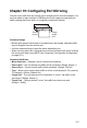
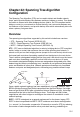
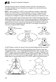
An MST Region consists of a group of interconnected bridges that have the same
MST Configuration Identifiers (including the Region Name, Revision Level and
Configuration Digest – see “Configuring Multiple Spanning Trees” on page 22-15).
An MST Region may contain multiple MSTP Instances. An Internal Spanning Tree
(IST) is used to connect all the MSTP switches within an MST region. A Common
Spanning Tree (CST) interconnects all adjacent MST Regions, and acts as a virtual
bridge node for communications with STP or RSTP nodes in the global network.
Region R
IST
(for this Region)
MST 1
MST 2
Region 1
Region 4
Region 2 Region 3
CIST
IST
Region 1
Region 4
Region 2 Region 3
CST