
Quick Start Guide

– 1 –
Quick Start Guide
E122022-CS-R01
www.edge-core.com
Indoor Wall-Plate Wi-Fi 6 Access Point
EAP104
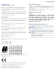
Package Contents
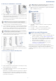
Mount the AP
a. Mounting on a Wall Junction Box
1. At the wall junction box, use two screws to secure the mounting
bracket to the box. The bracket must be installed with the marking
“UP” at the top.
2. Connect the Ethernet cable from the junction box to the Uplink (PoE)
RJ-45 port on the rear of the device. When connected to a PoE
source, the Uplink (PoE) port connection provides power to the unit.
3. With its ports facing down, place the AP over the bracket and then
slide it down until it is in its secured position.
4. Use the included security screw to secure the bracket to the AP.
5. (Optional) Connect a local LAN switch or computers to the LAN1 to
LAN4 1000BASE-T RJ-45 ports.
Warning:
For indoor use only. The access point, AC power
adapter, and all connected cables are not for outdoor use.
Note:
When not connected to a PoE source, you can power
the AP using the optional AC power adapter.
1
US/Japan/
Taiwan Box
EU Box
1
2
3
4
5
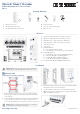
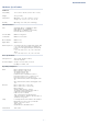
Overview
Installation
1. Pass-Thru Port: Bottom panel to rear panel connection.
2. LAN4 Port: 1Gbps LAN connection and PoE out port.
3. LAN1-LAN3 Ports: 1Gbps connection to LAN devices.
4. Uplink (PoE) Port: 1Gbps connection to 802.3at PoE.
5. 12 VDC power input
6. Console port
7. Restart/Reset button:
A quick press restarts the system.
Press and hold for 5 seconds resets to factory defaults.
8. System LED Indicators:
Uplink: Amber (1G), Green (100M), Blinking (traffic)
2.4G-WiFi: On (radio on), Blinking (traffic)
5G-WiFi: On (radio on), Blinking (traffic)
Cloud: On (cloud managed), off (standalone)
9. Power/Status LED: On (power OK), Blinking (boot up)
2
3
1
4
1
5
8
9
6
7
1. EAP104 access point
2. Mounting bracket accessory
3. Mounting bracket T8 security screw
4. RJ-45 short cable
5. Screw kit—4 screws and 4 plugs
6. QR code card
1 2 3 4 65