
- Accton 10 Slots L2/L3/L4 Chassis Switch


432
EES4710BD 10 Slots L2/L3/L4 Chassis Switch
Switch5(Config-if-vlan3)#exit
!Enable OSPF protocol, configure the number of the area in which interface vlan2 and vlan3
reside in.
Switch5(Config)#router ospf
Switch5(Config-router-ospf)#exit
Switch5(Config)#interface vlan 2
Switch5(Config-if-vlan2)#ip ospf enable area 0
Switch5(Config-if-vlan2)#exit
Switch5(Config)#interface vlan 3
Switch5(Config-if-vlan3)#ip ospf enable area 0
Switch5(Config-if-vlan3)#exit
Switch5(Config)#exit
Switch5#
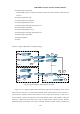
Scenario 2: Typical OSPF protocol complex topology.
Do mai n 2Do mai n 3
Do mai n 1
N3
N1
N8
N5
N6
N9
N1 0
N4
N2
N1 5
N1 4
N7
N1 2
N1 3N1 1
Do mai n 0
SWI T CH1
SWI T CH2
SWI T CH3
SWI T CH4
SWI T CH5
SWI T CH6
SWI T CH9
SWITCH12
SWI T CH1 1 S WI T CH1 0
SWI T CH7
SWI T CH8
Fig 18-4 Typical complex OSPF autonomous system.
Figure 18-4 is a typical complex OSPF autonomous system network topology. Area1 include
network N1-N4 and layer 3 switch Switch1-Switch4, area2 include network N5-N7 and layer 3
switch Switch7, Switch8, Switch10 and Switch11, area3 include N8-N10, host H1 and layer 3
switch Switch9, Switch11 and Switch12, and network N8-N10 share a same summary route with
host H1(i.e., define area3 and a STUB area). Layer 3 switch Switch1, Switch2, Switch5, Switch6,
Switch8, Switch9, Switch12 are in-area layer 3 switches, Switch3, Switch4, Switch7, Switch10 and