MR3202A IEEE 802.
User Guide Guide 802.11b/g Mini AP Router IEEE 802.
MR3202A E062007-EK-R01 149100038500E
Table of Contents Chapter 1: Introduction Package Checklist Hardware Description LED Indicators Ethernet RJ-45 Ports Power Socket Reset Button WPS SET Button Chapter 2: Installation Router Mode Bridge Mode 1-1 1-1 1-2 1-3 1-3 1-4 1-4 1-4 2-1 2-1 2-2 Chapter 3: Network Planning 3-1 Internet Gateway Router LAN Access Point Wireless Client Wireless Bridge 3-1 3-2 3-2 3-3 Chapter 4: Initial Configuration 4-1 Logging into the Web Interface Using the Setup Wizard 4-2 4-4 Chapter 5: System Configuration
Contents Wireless1 Wireless-VAP1 Settings MAC Filter Settings Wireless2 Wireless-VAP2 Settings WMM Settings QoS QoS Settings Advanced Settings DMZ Status System Interfaces Events Log DHCP Clients PPPoE Wireless Stations About Reboot 5-13 5-13 5-18 5-19 5-19 5-20 5-21 5-21 5-22 5-24 5-25 5-25 5-26 5-27 5-28 5-28 5-29 5-29 5-30 Appendix A: Troubleshooting A-1 Appendix B: Specifications B-1 Appendix C: License Information C-1 The GNU General Public License Glossary C-1
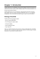
Chapter 1: Introduction The Mini AP Router is an IEEE 802.11b/g wireless gateway router that connects your Internet access device (cable or ADSL modem) to your PC or local area network, or to its own secure wireless network. The Mini AP Router can be automatically configured with other Wi-Fi Protected Setup (WPS) devices by simply pressing its WPS SET button. For more detailed configuration, the unit can also be set up through its easy-to-use web interface.
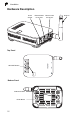
1 Introduction Hardware Description Power Socket Top Panel WPS SET Button Bottom Panel Wall Mount Slots Reset Button 1-2 Ethernet WAN RJ-45 Port Ethernet LAN RJ-45 Port Antenna
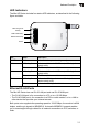
1 Hardware Description LED Indicators The Mini AP Router includes four status LED indicators, as described in the following figure and table. 802.11b/g Link/ Activity LAN Link/Activity WAN Link/Activity Power LED Status Description POWER On Green Indicates that the system is working normally. WAN On/Flashing Green Indicates a valid link on the WAN Ethernet port. Flashing indicates network activity. Off The Ethernet port has no valid link.
1 Introduction Power Socket The Mini AP Router does not have a power switch. It is powered on when connected to the AC power adapter, and the power adapter is connected to a power source. The power adapter automatically adjusts to any voltage between 100-240 volts at 50 or 60 Hz. No voltage range settings are required. Reset Button The Reset button can be used to restart the Mini AP Router or restore the factory default configuration.
Chapter 2: Installation The Mini AP Router has two basic operating modes that can be set through the web management interface: • Router Mode — Normal gateway mode that connects a wired LAN and wireless clients to an Internet access device, such as a cable or DSL modem. This is the factory set default mode. • Bridge Mode — An access point mode that extends a wired LAN to wireless clients.
2 Installation To connect the Mini AP Router in Router Mode for use as an Internet gateway, follow these steps: 1. Connect an Ethernet cable from the Mini AP Router’s WAN port to your Internet connected cable or ADSL modem. 2. Connect an Ethernet cable from the Mini AP Router’s LAN port to your PC. Alternatively, you can connect to a workgroup switch to support multiple users. The Mini AP Router can support up to 253 wired or wireless users. 3.
Bridge Mode 2 up 3 Set wireless devices Notebook PC Notebook PC LAN and WAN 1 Connect ports to Ethernet LAN switch or PCs 2 Connect AC power adapter to power source LAN Switch Server Desktop PCs To connect the Mini AP Router for use as an access point, follow these steps: 1. Connect an Ethernet cable from the Mini AP Router’s LAN or WAN port to your local network switch. 2. Power on the Mini AP Router by connecting the AC power adapter and plugging it into a power source.
2 2-4 Installation
Chapter 3: Network Planning The Mini AP Router is designed to be very flexible in its deployment options. It can be used as an Internet gateway for a small network, or as an access point to extend an existing wired network to support wireless users. It also supports use as a wireless client to connect to another wireless network, or a wireless bridge to connect two wired LANs.
3 Network Planning The public external network, connected to the WAN port, supports DHCP client and Point-to-Point Protocol over Ethernet (PPPoE) for connection to an Internet service provider (ISP) through a cable or DSL modem: LAN Access Point The Mini AP Router can provide an access point service for an existing wired LAN, creating a wireless extension to the local network. The Mini AP Router functions as purely an access point when set to Bridge Mode.
Wireless Bridge 3 Access Point (SSID: External) t Clien ) .x less Wire 92.168.2 rt (IP: 1 N Po .x) A /W LAN 92.168.1 (IP: 1 Mini AP Router Notebook PC (IP: 192.168.1.x) LAN Switch Server (IP: 192.168.1.x) Desktop PC (IP: 192.168.1.x) Wireless Bridge The IEEE 802.11 standard defines a WIreless Distribution System (WDS) for bridge connections between access points. The Mini AP Router can use WDS to forward traffic on links between units. A single WDS bridge link can be specified for each VAP interface.
3 3-4 Network Planning
Chapter 4: Initial Configuration The Mini AP Router offers a user-friendly web-based management interface for the configuration of all the unit’s features. Any PC directly attached to the unit can access the management interface using a web browser, such as Internet Explorer (version 6.0 or above). The initial configuration steps can be made through the web browser interface using the Setup Wizard.
4 Initial Configuration Logging into the Web Interface In the web browser’s address bar, type the default IP address: http://192.168.1.1. The web browser displays the home page. It is strongly recommended that you first set a password for web access. If a password is not configured, the management interface is not protected and your netowrk security may be compromised. To set up the password, follow these steps: 1. Launch the Advanced Setup – Click “Start with Advanced Setup.” Figure 4-1.
4 Logging into the Web Interface 2. Set the Password – Enter the new password and confirm it. Click the Set button. Figure 4-2. Password Setup 3. Login Page – When you next access the web interface, enter the default user name "root" and the password you have set, then click OK. Figure 4-3. Login Page 4. Return to the Home Page – From the home page, click Start with Setup Wizard and follow the simple steps to set up the Mini AP Router.
4 Initial Configuration Using the Setup Wizard There are only a few basic steps you need to set up the Mini AP Router and provide a connection for network access for other wireless stations. The Setup Wizard takes you through configuration procedures for the general network settings, such as IP configuration, wireless network name (Service Set Identifier), and wireless security. Follow these steps: 1. Launch the Setup Wizard – Click “Start with Setup Wizard” on the home page. 2.
Using the Setup Wizard 4 consist of four decimal numbers, 0 to 255, separated by periods. - Subnet Mask: The mask that identifies the host address bits used for routing to specific subnets. - Default Gateway – The IP address of the gateway router that is used if the requested destination address is not on the local subnet. - WAN DNS Server – The IP address of a Domain Name Server.
4 Initial Configuration - LAN IP Address – Valid IP addresses consist of four decimal numbers, 0 to 255, separated by periods.The default setting is 192.168.1.1. - Netmask – Indicate the local subnet mask is fixed as 255.255.255.0. - Default Gateway – Normally, for wireless clients and stations in the attached LAN, the gateway address is the same as the LAN IP address. For a larger LAN with stations located on other subnets, type the IP address of the default gateway router in the text field provided.
4 Using the Setup Wizard Wireless Configuration — Enables radio communications for the VAP interface. (Default: Enabled) • AP+WDS Parent – The VAP operates as an access point providing a WLAN for wireless clients. An AP using WDS can function as a wireless network bridge to allow a wireless connection between two wired network segments. - Broadcast SSID: Disables SSID broadcasting to protect your network from unauthorized access.
4 Initial Configuration Encryption Settings — Configures the encryption used by the VAP interface. • WEP – Enables the Mini AP Router to use WEP shared keys. If enabled, you must configure at least one key for the VAP interface and all its clients. Wired Equivalent Privacy (WEP) provides a basic level of security, preventing unauthorized access to the network and encrypting data transmitted between wireless clients and the Mini AP Router.
Using the Setup Wizard 4 Figure 4-9. Encryption Settings - WPA(PSK) Mode • WPA(RADIUS) or WPA / WPA2(RADIUS) – Enables WPA(RADIUS) or WPA / WPA2(RADIUS) security on the VAP interface. Remote Authentication Dial-in User Service (RADIUS) is an authentication protocol that uses software running on a central server to control access to RADIUS-aware devices on the network. An authentication server contains a database of user credentials for each user that requires access to the network.
4 Initial Configuration 5. Wireless-VAP2 Configuration — Sets the wireless Service Set Identifier (SSID) and wireless security encryption key for the VAP2 wireless network. Figure 4-11. Setup Wizard - Wireless-VAP2 Settings Please refer to the page 4-6 to 4-9 for the details of the displayed items on this page.
Chapter 5: System Configuration The Mini AP Router’s basic settings can be configured using the Setup Wizard, as described in the previous chapter, “Initial Configuration.” However, for some installations, you may need to configure specific settings that are not available in the Setup Wizard. The Advanced Setup menu provides access to all the unit’s settings for complete control of the Mini AP Router’s features. To access the Advanced Setup menus, follow these steps: 1.
5 System Configuration The Advanced Setup pages include the options in the table below. For details on configuration for each feature, see the corresponding page number. Table 5-1.
5 System Table 5-1. Configuration Options Menu Description Page Wireless Stations Displays the wireless station status 5-29 About Displays the software information 5-29 Reboot 5-30 System The system pages allow you to conduct the management of basic system configuration settings. Settings The system settings page allows you to set the operation mode, time and web interface display language. Figure 5-2.
5 System Configuration • Router – Set the device as a Wireless Router that acts as a junction between two or more networks to buffer and transfer data packets among them. Time Settings — Set the timezone and NTP server of the Mini AP Router. • Timezone – Set your local time zone according to the location. • NTP Server – Configure the IP address of an NTP time server that the Mini AP Router attempts to poll for a time update. Webif Settings — Set the language display of the web interface.
5 System Backup and Restore The backup and resotre page allows you to backup your current configuration of the Mini AP Router and resotre the previously set configuration back to the device. Figure 5-4. Backup and Restore The displayed items on this page can be described as follows: Download Configuration — Download the current configuration. • Name this configuration – Type a file name for the current configuration. Click Download button to generate the configuration file.
5 System Configuration DynDNS Settings Dynamic DNS (DDNS) provides users on the Internet with a method to tie a specific domain name to the unit’s dynamically assigned IP address. DDNS allows your domain name to follow your IP address automatically by changing your DNS records when your IP address changes. Figure 5-5. DynDNS Settings The displayed items on this page can be described as follows: DynDNS — Enable the Dynamic DNS of the Mini AP Router. • Service Provider – Specify the DDNS service provider.
System 5 Syslog Settings The Mini AP Router supports a logging process that can control error messages saved to memory or sent to a Syslog server. The logged messages serve as a valuable tool for isolating Mini AP Router and network problems. Figure 5-6. Syslog Settings The displayed items on this page can be described as follows: Remote Syslog — Set the operation mode of the Mini AP Router. • Server IP Address – The IP address or name of a Syslog server.
5 System Configuration Firmware Upgrade The upgrade page allows you to download a new software code file from the local web management station to the Mini AP Router using HTTP. After upgrading to new software, you must reboot the Mini AP Router to implement the new code. Until a reboot occurs, the Mini AP Router will continue to run the software it was using before the upgrade started. Figure 5-7.
5 WAN WAN Specify the WAN connection parameters provided by your Internet Service Provider (ISP). WAN Settings Specifies the type of WAN connection to use. The selected option depends on the device connected to the WAN port and your specific ISP service. Figure 5-8. WAN Settings The displayed items on this page can be described as follows: WAN Configuration — Set the IP address configuration of the Mini AP Router.
5 System Configuration consist of four decimal numbers, 0 to 255, separated by periods. - Subnet Mask: The mask that identifies the host address bits used for routing to specific subnets. - Default Gateway – The IP address of the gateway router for the Mini AP Router, which is used if the requested destination address is not on the local subnet. - WAN DNS Server – The IP address of a Domain Name Server on the service provider’s network.
5 LAN LAN The Mini AP Router must have a valid IP address for management using a web browser and to support other features. The unit has a default IP address of 192.168.1.1. You can use this IP address or assign another address that is compatible with your existing local network. The unit can also be enabled as a Dynamic Host Configuration Protocol (DHCP) server to allocate IP addresses to local PCs and wireless clients. The unit can support up to 253 local clients.
5 System Configuration gateway router in the text field provided. Otherwise, leave the address as (192.168.1.1). DHCP Service for LAN — Set the DHCP service configuration of the Mini AP Router. • DHCP Service – Enable the DHCP server. • DHCP Start – Specify the start IP address of a range that the DHCP server can allocate to DHCP clients. Note that the address pool range is always in the same subnet as the unit’s IP setting.
5 Wireless1 Wireless1 Set the wireless WLAN mode and wireless security for the Wireless-VAP1 network. Wireless-VAP1 Settings The Wireless-VAP1 Settings page includes configuration options for radio signal characteristics and wireless security features on the Mini AP Router. The Wireless-VAP1 interface is enabled by default. Figure 5-10.
5 System Configuration Clients that want to connect to the network must set their SSID to the same as that of the VAP interface. (Default: “Wireless Network 1” for VAP1; “Wireless Network 2” for VAP2; Range: 1-32 characters) - Channel: The radio channel that the Mini AP Router uses to communicate with wireless clients. When multiple access points are deployed in the same area, set the channel on neighboring access points at least five channels apart to avoid interference with each other.
Wireless1 5 Note: This WLAN Mode is only availabe when the operation mode is set to Bridge. Only one of the two Wireless VAPs can be set to WDS Child mode and the other must be set to AP+WDS. Figure 5-12. Wireless-VAP1 Settings (WDS Child Mode) Encryption Settings — Configures the encryption used by the client. • WEP – Enables the Mini AP Router to use WEP shared keys. If enabled, you must configure at least one key for the VAP interface and all its clients.
5 System Configuration Figure 5-13. Encryption Settings - WEP Mode • WPA(PSK) – Enable WPA(PSK) security on the VAP interface. Wi-Fi Protected Access (WPA) employs a combination of technologies to provide an enhanced security solution for wireless networks. The WPA Pre-shared Key (WPA-PSK) mode for small networks uses a common password phrase that must be manually distributed to all clients that want to connect to the network.
Wireless1 5 function as pressing the physical WPS SET Button on the Mini AP Router. Note: The Wi-Fi Protected Setup is avaliable for VAP1 only. Figure 5-15. Encryption Settings - WPA/WPA2(PSK) Mode • WPA(RADIUS) or WPA / WPA2(RADIUS) – Enables WPA(RADIUS) or WPA / WPA2(RADIUS) security on the VAP interface. Remote Authentication Dial-in User Service (RADIUS) is an authentication protocol that uses software running on a central server to control access to RADIUS-aware devices on the network.
5 System Configuration MAC Filter Settings You can allow or block access to the Internet from clients on the local network by MAC addresses. Figure 5-17. Encryption Settings - WPA(RADIUS) Mode The displayed items on this page can be described as follows: • Filter Mode – Allow or deny the feature. • White List – Specify a local PC MAC address. Click Add to add a MAC address to the filter list or click Remove to delete it from the list.
5 Wireless2 Wireless2 Sets the wireless Service Set Identifier (SSID) and wireless security encryption key for the Wireless-VAP2 network. An SSID is a recognizable text name that identifies a wireless network. Wireless clients that want to connect to the network must set their SSIDs to match that of the router. Wireless-VAP2 Settings The Wireless-VAP2 Settings page includes configuration options for radio signal characteristics and wireless security features on the Mini AP Router.
5 System Configuration WMM Settings Wi-Fi Multimedia (WMM), also known as Wireless Multimedia Extensions (WME), is a Wi-Fi Alliance interoperability certification. It provides basic Quality of Service (QoS) features for IEEE 802.11 wireless network. The WMM settings page allows you to enable the WMM service. The specification provides prioritization of data packets based on four categories - voice, video, best effort, and background. Figure 5-19.
5 QoS QoS Wireless networks offer an equal opportunity for all devices to transmit data from any type of application. Although this is acceptable for most applications, multimedia applications (with audio and video) are particularly sensitive to the delay and throughput variations that result from this equal opportunity wireless access method.
5 System Configuration these values at between 85-90% of your true speeds. Most broadband services are rated in Megabits per second (Mbps). To convert Mbps to Kilobits per second (Kbps), multiply the value by 1024. The following table lists the most common broadband service speeds.: Mbps 1 2 3 4 6 8 12 Kilobits 1024 2048 3072 4069 6144 8192 12288 Advanced Settings The advanced settings page allows you to edit or create QoS Traffic Classfication Rules. Figure 5-21.
5 QoS Qos Traffic Classification Rules – A traffic classification rule can classify traffic according to the traffic classification policy set by the network administrator, such as the combination of source addresses, destination addresses, MAC addresses, IP protocol or the port numbers of the applications. Click edit or remove to modify the rules, or click “new rule” to create a new traffic classification rule. Qos Rule Edit — Set the fields that you wish to match traffic on. Leave the others blank.
5 System Configuration DMZ If you have a client PC that cannot run an Internet application properly from behind the NAT firewall, you can open the client up to unrestricted two-way internet access by defining a virtual-DMZ (virtual-demilitarized-zone) host. Figure 5-22. DMZ Settings The displayed items on this page can be described as follows: • DMZ Service – Enables the DMZ feature. (Default: Disabled) • DMZ IP Address – Specifies the IP address of the virtual DMZ host.
5 Status Status The status pages display details on the current configuration and status of the Mini AP Router, including associated wireless stations and event log messages. System The system page displays basic system configuration settings. The displayed settings are for status information only and are not configurable on this page. Figure 5-23.
5 System Configuration • ESSID – The service set identifier for this wireless group. • Frequency – The The channel frequency being used by the radio. • Encryption – The encryption used by the VAP interface. Interfaces The Interfaces page displays the settings for each wireless interface. The displayed settings are for status information only and are not configurable on this page. Figure 5-24.
5 Status • Received – The received LAN radio signal frequency. • Transmitted – The radio frequency of the WLAN transmission. WLAN – Display the wireless interface settings. • VAP1/VAP2 – The status of the Configuration. • ESSID – The service set identifier for this wireless group. • Frequency – The radio frequency of the WLAN transmission. • Transmit Power – The power of the radio signals transmitted from the Mini AP Router. The higher the transmission power, the farther the transmission range.
5 System Configuration DHCP Clients The network information page displays the current Dynamic Host Configuration Protocol (DHCP) clients status. The displayed settings are for status information only and are not configurable on this page. Figure 5-26. DHCP Client Settings PPPoE The PPPoE Status page page displays the current Point-to-Point Protocol over Ethernet (PPPoE) status. The displayed settings are for status information only and are not configurable on this page. Figure 5-27.
5 Status Wireless Stations The Wireless Stations page page displays the wireless station status. The displayed settings are for status information only and are not configurable on this page. Figure 5-28. Wireless Stations About The About page displays the software version and status installed in the Mini AP Router. Figure 5-29.
5 System Configuration Reboot The Reboot page allows you to restart the Mini AP Router software and restore factory default settings. Figure 5-30. Reboot The displayed items on this page can be described as follows: • Reboot Mini AP Router – Click the Reboot button to reboot the system. • Restore Factory Settings – Click the Factory Reset button to reset the configuration settings for the Mini AP Router to the factory defaults and reboot the system. Note that all user configured information will be lost.
Appendix A: Troubleshooting Check the following items before you contact local Technical Support. 1. If wireless clients cannot access the network, check the following: • Be sure the access point and the wireless clients are configured with the same Service Set ID (SSID). • If authentication or encryption are enabled, ensure that the wireless clients are properly configured with the appropriate authentication or encryption keys. 2.
A Troubleshooting Diagnosing LED Indicators Troubleshooting Chart Symptom Action POWER LED is Off • The AC power adapter may be disconnected. Check connections between the Mini AP Router, the power adapter, and the wall outlet. WLAN LED is Off • The Mini AP Router’s radio has been disabled through it’s web management interface. Access the management interface using a web browser to enable the radio.
Appendix B: Specifications Wireless Output Power 802.11b: 18 dBm (typical) 802.11g: 17 dBm @ 6 Mbps, 14dBm @ 54 Mbps Wireless Receive Sensitivity 802.11b: -90 dBm @ 1 Mbps, -84 dBm @ 11 Mbps 802.11g: -86 dBm @ 6 Mbps, -68 dBm @ 54 Mbps Operating Frequency 802.11g: 2.4 ~ 2.4835 GHz (US, Canada) 2.4 ~ 2.4835 GHz (ETSI, Japan) 802.11b: 2.4 ~ 2.4835 GHz (US, Canada) 2.4 ~ 2.4835 GHz (ETSI) 2.4 ~ 2.497 GHz (Japan) Data Rate 802.11g: 6, 9, 12, 18, 24, 36, 48, 54 Mbps per channel 802.11b: 1, 2, 5.
B Specifications Network Management Web-browser Temperature Operating: 0 to 40 °C (32 to 104 °F) Storage: -20 to 70 °C (32 to 158 °F) Humidity 15% to 95% (non-condensing) Compliances FCC Part 15B Class B EN 55022B EN 55024 EN61000-3-2 EN61000-3-3 VCCI Class B Radio Signal Certification FCC Part 15C 15.247, 15.207 (2.4 GHz) EN 300 328 EN 301 489-1 EN 301 489-17 ARIB STD-T66 IC RSS-210 Standards IEEE 802.1 x IEEE 802.11b, g IEEE 802.3 Wi-Fi 11b/g, WPA, WPA2, WMM Physical Size 12.5 x 7 x 2.7 cm (4.
Appendix C: License Information This product includes copyrighted third-party software licensed under the terms of the GNU General Public License. Please refer to the section “The GNU General Public License” for the exact terms and conditions of this license.
C License Information certain responsibilities for you if you distribute copies of the software, or if you modify it. For example, if you distribute copies of such a program, whether gratis or for a fee, you must give the recipients all the rights that you have. You must make sure that they, too, receive or can get the source code. And you must show them these terms so they know their rights.
The GNU General Public License C You may charge a fee for the physical act of transferring a copy, and you may at your option offer warranty protection in exchange for a fee. 3. You may modify your copy or copies of the Program or any portion of it, thus forming a work based on the Program, and copy and distribute such modifications or work under the terms of Section 1 above, provided that you also meet all of these conditions: a).
C License Information b). Accompany it with a written offer, valid for at least three years, to give any third party, for a charge no more than your cost of physically performing source distribution, a complete machine-readable copy of the corresponding source code, to be distributed under the terms of Sections 1 and 2 above on a medium customarily used for software interchange; or, c). Accompany it with the information you received as to the offer to distribute corresponding source code.
The GNU General Public License 8. C If, as a consequence of a court judgment or allegation of patent infringement or for any other reason (not limited to patent issues), conditions are imposed on you (whether by court order, agreement or otherwise) that contradict the conditions of this License, they do not excuse you from the conditions of this License.
C License Information Free Software Foundation; we sometimes make exceptions for this. Our decision will be guided by the two goals of preserving the free status of all derivatives of our free software and of promoting the sharing and reuse of software generally. NO WARRANTY 1. BECAUSE THE PROGRAM IS LICENSED FREE OF CHARGE, THERE IS NO WARRANTY FOR THE PROGRAM, TO THE EXTENT PERMITTED BY APPLICABLE LAW.
Glossary 10BASE-T IEEE 802.3 specification for 10 Mbps Ethernet over two pairs of Category 3 or better UTP cable. 100BASE-TX IEEE 802.3u specification for 100 Mbps Fast Ethernet over two pairs of Category 5 or better UTP cable. Access Point An internetworking device that seamlessly connects wired and wireless networks. Access points attached to a wired network, support the creation of multiple radio cells that enable roaming throughout a facility.
Glossary Encryption Data passing between the access point and clients can use encryption to protect from interception and evesdropping. Ethernet A popular local area data communications network, which accepts transmission from computers and terminals. File Transfer Protocol (FTP) A TCP/IP protocol used for file transfer. Hypertext Transfer Protocol (HTTP) HTTP is a standard used to transmit and receive all data over the World Wide Web. IEEE 802.
Glossary Orthogonal Frequency Division Multiplexing (ODFM) OFDM allows multiple users to transmit in an allocated band by dividing the bandwidth into many narrow bandwidth carriers. Repeater and Bridge Repeater and bridge can provide an extended link to a remote access point from the wired LAN. Access Point working in this mode could connect to another AP in Access Point mode or Repeater and Bridge mode.
Glossary single radio channel, enabling Virtual AP technology to optimize the use of limited WLAN radio spectrum. Wi-Fi Protected Access WPA employs 802.1X as its basic framework for user authentication and dynamic key management to provide an enhanced security solution for 802.11 wireless networks. Wired Equivalent Privacy (WEP) WEP is based on the use of security keys and the popular RC4 encryption algorithm. Wireless devices without a valid WEP key will be excluded from network traffic.
MR3202A E062007-EK-R01 149100038500E
Federal Communication Commission Interference Statement This equipment has been tested and found to comply with the limits for a Class B digital device, pursuant to Part 15 of the FCC Rules. These limits are designed to provide reasonable protection against harmful interference in a residential installation. This equipment generates, uses and can radiate radio frequency energy and, if not installed and used in accordance with the instructions, may cause harmful interference to radio communications.
bands are country dependent and are firmware programmed at the factory to match the intended destination. The firmware setting is not accessible by the end user.
Europe – EU Declaration of Conformity This device complies with the essential requirements of the R&TTE Directive 1999/5/EC.
Español [Spanish] Por medio de la presente [nombre del fabricante] declara que el [clase de equipo] cumple con los requisitos esenciales y cualesquiera otras disposiciones aplicables o exigibles de la Directiva 1999/5/CE. Ελληνική [Greek] ΜΕ ΤΗΝ ΠΑΡΟΥΣΑ [name of manufacturer] ΔΗΛΩΝΕΙ ΟΤΙ [type of equipment] ΣΥΜΜΟΡΦΩΝΕΤΑΙ ΠΡΟΣ ΤΙΣ ΟΥΣΙΩΔΕΙΣ ΑΠΑΙΤΗΣΕΙΣ ΚΑΙ ΤΙΣ ΛΟΙΠΕΣ ΣΧΕΤΙΚΕΣ ΔΙΑΤΑΞΕΙΣ ΤΗΣ ΟΔΗΓΙΑΣ 1999/5/ΕΚ.