
User's Manual
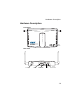
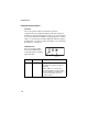
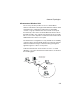
Table Of Contents
- Chapter 1 Introduction
- Chapter 2 Network Configuration
- Chapter 3 Hardware Installation
- Chapter 4 Initial Configuration
- Chapter 5 System Configuration
- Chapter 6 Command Line Interface
- Using the Command Line Interface
- Entering Commands
- Command Groups
- General Commands
- System Management Commands
- SNMP Commands
- Flash/File Commands
- RADIUS Client
- 802.1x Port Authentication
- Filtering Commands
- Interface Commands
- interface
- dns server
- ip address
- ip dhcp
- shutdown
- speed-duplex
- show interface ethernet
- radio-mode
- select-antenna-mode
- description
- ssid-broadcast
- closed-system
- speed
- channel
- ssid
- beacon-interval
- dtim-period
- fragmentation-length
- rts-threshold
- authentication
- encryption
- key
- transmit-key
- transmit-power
- max-association
- multicast-cipher
- wpa-clients
- wpa-mode
- wpa-preshared-key
- wpa-psk-type
- shutdown
- show interface wireless
- show station
- IAPP Commands
- VLAN Commands
- Appendix A Troubleshooting
- Appendix B Specifications
- Appendix C Cables and Pinouts
- Glossary
- Index

Introduction
1-4
Component Description
Antennas
The access point includes two antennas for wireless
communications. The signal transmitted from both antennas is
identical, but only the best signal received on one of the antennas
is used. The antennas transmit the outgoing signal as a toroidal
sphere, so the antennas should be adjusted to different angles to
provide better coverage. For further information, see “Positioning
the Antennas” on page 2-3.
LED Indicators
The access point includes
three status LED indicators,
as described in the following
figure and table.
LED Status Description
LED1 Green/Amber Off: No power.
Green On: Power On and Ready for
Operation.
Amber: H/W error or system error.
Slow Green Blink: Power On but Not
Ready for Operation-at initial power on
or reset, this indicates self-test or
software loading.
WLAN
LAN
Power
802.11g
Wireless
Link/Activity
Ethernet
Link/Activity