Powered by Accton EC3002 Media Converter Installation Guide www.edge-core.
Installation Guide FTTH Media Converter - EC3002 with One Fixed 100BASE-FX Single-Fiber Line Connection, and One 10BASE-T / 100BASE-TX (RJ-45) Port
EC3002 E062005-R01 150000047700A
Contents Introduction Key Features 1 2 Description of Hardware Fiber Cable Connection UTP Port External DIP Switch Settings Internal DIP Switch Settings LED Indicators 3 3 3 4 5 6 Installing the FTTH CPE Package Contents System Requirements Mounting the CPE Desktop Mounting Wall Mounting Connecting to the CPE Making a Connection to the UTP Port Powering On the CPE Configuring the TCP/IP Protocol Windows 95/98/NT Windows 2000 Windows XP Mac OS Systems 7 7 7 8 9 9 10 10 11 12 12 12 12 13 Product Specifi
Contents ii
Introduction Fiber-To-The-Home (FTTH) has always been an attractive option for Internet access. It has all the benefits of optical fiber. It provides a future-proof network, in that you do not have to go through the hassles of upgrading from ADSL to xDSL, or digital co-ax to digital wireless. It does not have to struggle with electromagnetic interference problems, and with no active “outside-plant” components, it offers the highest reliability.
Introduction Key Features • • • • • • • • • • • • • • • • 2 High-speed Internet access Optical fiber port supports transmission distances up to 15 km Built-in transparent bridging between different media segments Supports 1K MAC addresses — forwards packets only if necessary Always-on fast optical fiber connection eliminates dial-up delays, providing transparent Internet access Auto-negotiating 10/100BASE-TX Ethernet port Provides DIP switch setting to force 10/100BASE-TX port speed, duplex mode, and MDI
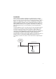
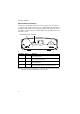
Description of Hardware The EC3002 is an FTTH CPE product for high-speed Internet access applications. The CPE includes an embedded fiber cable connection, an RJ-45 Ethernet port, a DIP-switch for the RJ-45 port settings, an internal DIP switch for Auto MDI-X, flow control, MAC learning and Link Pass Through, LED status indicators, and an AC power adapter connection. The following figure shows the components of the CPE.
Description of Hardware External DIP Switch Settings The CPE has a four-bit DIP switch located on its rear panel next to the UTP port (see figure below). The DIP switch allows you to enable/disable auto-negotiation for the UTP port and manually force the speed and duplex mode setting. Also, there is one switch for setting the UTP port to MDI or MDI-X wiring. The ON position for the DIP switch is down.
Internal DIP Switch Settings Internal DIP Switch Settings The CPE has a second four-bit DIP switch located internally next to the LEDs (see figure below). This DIP switch sets the capabilities available to the external DIP switch and allows flow control to be enabled/disabled. The ON position for the DIP switch is down.
Description of Hardware LED Indicators The CPE includes seven LED status indicators on the top panel. The LEDs are detailed in the following figure and table. LED Color Description PWR Green ON: Power is on. OFF: Power is off. OPT Green ON: Fiber link is up. OFF: Fiber link down. TEST Orange ON: Loopback test in progress. OFF: No loopback test (normal mode). PC Green ON: UTP port link is up. OFF: UTP port link is down. DATA Green ON/Flashing: UTP port is transmitting or receiving data.
Package Contents Installing the FTTH CPE Before installing the CPE, verify that you have all the items listed under “Package Contents.” If any of the items are missing or damaged, contact your service provider. Also, be sure you have all the necessary tools and cabling before installing the CPE.
Installing the FTTH CPE Mounting the CPE Caution: The EC3002 CPE is for indoor mounting only. Do not mount the unit on the outside of a building. The CPE includes rubber feet for desktop mounting. Horizontal mounting using rubber feet Desktop Mounting Wall mounting using the wall-mounting slots Wall Mounting Before you start installing the CPE, make sure you can provide the right operating environment.
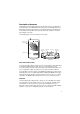
Mounting the CPE Desktop Mounting The CPE can be mounted horizontally on any flat surface, such as a desktop or shelf. For horizontal mounting, simply stick the self-adhesive rubber foot pads (that come with this package) on each of the four concave spaces located on the bottom of the CPE. Then, place the CPE on the flat surface where it is to be installed. Rubber feet Bottom surface Wall Mounting The CPE can also be mounted on a wall.
Installing the FTTH CPE Connecting to the CPE Caution: The CPE fiber line should be connected to the unit by a qualified technician only. Do not attempt to remove the fiber cable from the CPE. If there are any problems with the fiber cable connection, contact your service provider. You can connect any computer with an Ethernet network interface card, a LAN switch, hub, or other network device to the CPE’s UTP port.
Powering On the CPE 4. Connect one end of the cable to the RJ-45 port of the computer’s network interface card, and the other end to the UTP port on the CPE. When inserting an RJ-45 plug, be sure the tab on the plug clicks into position to ensure that it is properly seated. Notes: 1. Make sure each twisted-pair cable does not exceed 100 meters (328 feet). 2.
Installing the FTTH CPE Configuring the TCP/IP Protocol To connect to the Internet through the CPE’s Ethernet port, a computer must have an Ethernet network interface card installed, and be configured for the TCP/IP protocol. Many service providers will configure TCP/IP for client computers automatically using a networking technology known as Dynamic Host Configuration Protocol (DHCP). Other service providers may specify an IP configuration (known as a static IP address), which must be entered manually.
Mac OS Systems 1. Pull down the Apple Menu. Click “Control Panels” and select “TCP/IP.” 2. In the TCP/IP dialog box, make sure that “Ethernet” is selected in the “Connect via:” field. 3. If “Using DHCP Server” is already selected in the “Configure” field, your computer is already configured for DHCP. Otherwise, select “Using DHCP Server” in the “Configure” field and close the window. 4. Another box will appear asking whether you want to save your TCP/IP settings. Click Save.
Product Specifications Product Specifications Standards Conformance Fiber Specifications Fiber Cable Connector Wavelengths Data Rate Transmit Power Receive Power Optical Power Budget Range Ports Media Connection LEDs IEEE 802.3 10BASE-T, IEEE 802.3u 100BASE-TX and 100BASE-FX, IEEE 802.3x flow control TTC Standard TS-1000 class S ITU-T G.
Diagnosing CPE Indicators Troubleshooting Diagnosing CPE Indicators The FTTH CPE can be easily monitored through panel indicators to identify problems. The table below describes common problems you may encounter and possible solutions. Symptom Cause Solution Power indicator does Power outlet, or external • Check the power outlet by plugging in another device not light up after power AC power adapter may that is functioning properly. on. be defective. • Contact your FTTH service provider.
Port and Cable Assignments Port and Cable Assignments RJ-45 Ethernet Port Caution: DO NOT plug a phone jack connector into any RJ-45 port. Use only twisted-pair cables with RJ-45 connectors that conform with FCC standards. An Ethernet twisted-pair link segment requires two pairs of wires. Each wire pair is identified by two different colors. Each wire pair must be attached to the RJ-45 connector in a specific orientation detailed below.
RJ-45 Ethernet Port EIA/TIA 568B RJ-45 Wiring Standard 10/100BASE-TX Straight-through Cable White/Orange Stripe Orange End A 1 2 3 4 5 6 7 8 White/Green Stripe Blue White/Blue Stripe Green White/Brown Stripe 1 2 3 4 5 6 7 8 End B Brown Crossover Wiring If the twisted-pair cable is to join two ports and either both ports are labeled with an “X” (MDI-X) or neither port is labeled with an “X” (MDI), a crossover must be implemented in the wiring.
EMI Certification EMI Certification Safety Compliance FCC - Class B This equipment generates, uses, and can radiate radio frequency energy and, if not installed and used in accordance with the instruction manual, may cause interference to radio communications.
Wichtige Sicherheitshinweise (Germany) Wichtige Sicherheitshinweise (Germany) 1. 2. 3. 4. 5. 6. 7. 8. 9. 10. 11. 12. 13. 14. Bitte lesen Sie diese Hinweise sorgfältig durch. Heben Sie diese Anleitung für den späteren Gebrauch auf. Vor jedem Reinigen ist das Gerät vom Stromnetz zu trennen. Verwenden Sie keine Flüssigoder Aerosolreiniger. Am besten eignet sich ein angefeuchtetes Tuch zur Reinigung. Die Netzanschlu ßsteckdose soll nahe dem Gerät angebracht und leicht zugänglich sein.
EMI Certification 20
EC3002 E062005-R01 150000047700A