
User's Manual

4/3/03 Accton Draft—CONFIDENTIAL
18 Aruba 50 Part 0500007A
Installation Guide May 2003
Connect Required Cables
The cables required for operating the Aruba 50 depend on your intended network topology
(see
Figure 2-1 on page 8) and on the physical location.
Direct SPOE to the Aruba WLAN Switch
Use this procedure when connecting the Aruba 50 directly to an SPOE-compatible network
port on the Aruba WLAN Switch (see
“Power Over Ethernet” on page 2). SPOE provides
10/100 Mbps Ethernet, serial connection, and power over one cable.
NOTE—
If connecting the Aruba 50 through the LAN or to a non-SPOE network port on
the Aruba WLAN Switch, see the instructions on
page 19.
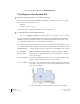
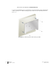
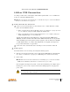
Connect the included SPOE adapter to the Aruba 50.
Connect the adapter’s 9-pin serial connector to the Console port on the back of the
Aruba 50.
Connect the adapter’s male RJ-45 plug to the FE port on the back of the Aruba 50.
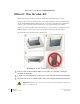
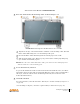
Connect the Aruba 50 to the Aruba WLAN Switch.
The connection between the Aruba 50 and the Aruba WLAN Switch requires an 8-conduc-
tor, Category 5 UTP, straight-through FE cable with RJ-45 connectors (see
Appendix B for
port specifications).
Any FE cable installed in an air-handling space, as described in NEC (2002) Article 300.22(C),
should be suitable under NEC Article 800.50 and marked accordingly for use in plenums and
air-handling spaces with regard to smoke propagation, such as CL2-P, CL3-P, MPP or CMP.
Install cables in accordance with all applicable local regulations and practices.
Connect one end of the FE cable directly to the RJ-45 socket on the SPOE adapter that
was attached to the Aruba 50 in the previous step.
Connect the other end of the FE cable directly to an available SPOE network port on the
Aruba WLAN Switch.
N
OTE—
The Aruba 50 must be connected to the Aruba WLAN Switch without any inter-
vening hubs, routers, or other networking equipment.
1
A
B
2
A
B