Using the Setup Wizard 4 • L2TP Password: Sets a L2TP password for the WAN port. (Default: L2TP_PASSWORD; Range: 1~32 characters) Bigpond Enables the settings of Telstra Bigpond network service in Australia. The following example shows the dual WAN function enabled using 3G as a secondary WAN connection. Figure 4-14. Setup Wizard - WAN Bigpond • Bigpond Username: Sets the Bigpond user name for the WAN port.
4 4. Initial Configuration WLAN Setting – Enables the wireless interface, selects the operating channel and configures SSIDs for both VAPs. Click Next after completing the setup. Figure 4-15. Setup Wizard - WLAN Configuration The displayed items on this page can be described as follows: • WLAN – Enables the communication for the VAP wireless interface. (Default: Enabled) • WLAN Mode – Defines the radio mode for the VAP interface. See “WLAN Mode” on page 5-21 for more information. (Default: 802.
4 Using the Setup Wizard 5. WLAN1/WLAN2 Security — Sets the wireless security encryption key for the wireless network. Figure 4-16. Setup Wizard - WLAN1 Security Authentication Mode – Configures the authentication mode used by clients. See “Authentication Mode” on page 5-28 for more information. (WLAN1/WLAN2 Defaults: Open) 6. Click Finish & Reboot after completing the configuration changes.
4-14 Initial Configuration
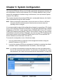
Chapter 5: System Configuration The wireless AP/Router offers a user-friendly web-based management interface for the configuration of all the unit’s features. Any PC directly attached to the unit can access the management interface using a web browser, such as Internet Explorer (version 6.0 or above). This chapter describes the wireless AP/Router’s configurable features, all of which may be accessed through the web interface.
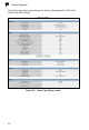
5 System Configuration The System Information page displays the System, Management IP, WAN, LAN, WLAN, and WDS settings. Figure 5-2.
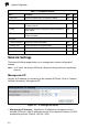
5 The information in this chapter is organized to reflect the structure of the web management screens for easy reference. The Configuration pages include the options in the table below. For details on configuration for each feature, see the corresponding page number. Note: The displayed pages and settings may differ depending on whether the unit is in Router or AP Mode. Table 5-1.
5 System Configuration Table 5-1.
5 WAN Setting • Subnet Mask – Indicates the local subnet mask. Select the desired mask from the drop down menu. (Default: 255.255.255.0) WAN Setting Specifies the Internet connection parameters. Click on “Network Settings” followed by “WAN.” WAN Connection By default, the access point WAN port is configured with DHCP enabled. After you have network access to the access point, you can use the web browser interface to modify the initial IP configuration, if needed.
5 System Configuration WAN Ethernet Speed — Configures the WAN Ethernet connection speed. (Default: Auto-Negotiated) • Auto-Negotiated – Enables auto-negotiation. • 100Mbps, Full-Duplex – Forces 100 Mbps full-duplex operation. • 100Mbps, Half-Duplex – Forces 100 Mbps half-duplex operation. • 10Mbps, Full-Duplex – Forces 10 Mbps full-duplex operation. • 10Mbps, Half-Duplex – Forces 10 Mbps half-duplex operation. WAN Ethernet MAC — Some ISPs limit Internet connections to a specified MAC address of one PC.
5 WAN Setting DHCP DHCP (dynamic host control protocol) is set as default for the primary WAN connection. To enable DHCP for the Backup WAN you must select 3G as the primary WAN connection. Figure 5-5. WAN Settings for DHCP (Router mode) DHCP — Enables DHCP for the WAN port. • DHCP MTU: Sets the maximum packet size that the WAN port may transmit. The Maximum Transmission Unit (MTU) is expressed in bytes.
5 System Configuration Static IP Configures the unit to use the same IP address each time it connects. Figure 5-6. WAN Settings for Static IP (Router mode) Static IP — Configures a static IP for the WAN port. • Static IP MTU: Sets the maximum packet size that the WAN port may transmit. The Maximum Transmission Unit (MTU) is expressed in bytes.
WAN Setting 5 • WAN IP Alias – Adds more than one IP address to the network interface for multiple connectivity. - Enable: Enables the specified IP address. - Add: Specifies a WAN IP alias. - Change: Changes the already specified IP alias. - Delete: Deletes the IP alias. PPPoE Enable the wireless AP/Router IP address to be assigned automatically from an Internet service provider (ISP) through an ADSL modem using Point-to-Point Protocol over Ethernet (PPPoE). Figure 5-7.
5 System Configuration PPPoE — Configures PPPoE. • PPPoE MTU: Sets the maximum packet size that the WAN port may transmit. The Maximum Transmission Unit (MTU) is expressed in bytes. (Default:1492 bytes) • PPPoE MRU: Sets the maximum packet size that the unit may receive from other units on the network and sends a message to inform them of the set threshold. Maximum Receive Unit (MRU) is expressed in bytes.
WAN Setting 5 3G 3G technologies enable cellular network operators to offer users a wider range of more advanced services while achieving greater network capacity through improved spectral efficiency. Services include wide-area wireless voice telephony, video calls, and broadband wireless data, all in a mobile environment. To use the 3G option, you need to first connect a 3G/3.5G USB modem to the USB port on the back of the unit and have registered an account with a cellular operator. Figure 5-8.
5 System Configuration 3G — Enables a 3G/3.5G wide-area wireless cellular link on the USB port using an optional USB modem. • Pin Code Protect: Enables the use of a PIN code (personal identification number) to encrypt access to the wireless 3G connection. Some service providers do not require PIN code authentication. If the PIN code for your 3G/3.5G modem is disabled, then disable this function. (Default: Enabled) • Pin Code: Specifies a PIN code number that corresponds with that set on your 3G/ 3.
5 WAN Setting PPTP Enable the Point-to-Point Tunneling Protocol (PPTP) for implementing virtual private networks. The service is provided across the Internet in many European countries. The following example shows PPTP selected as the primary WAN connection with 3G enabled as a backup WAN. Figure 5-9. WAN Settings for PPTP (Router mode) PPTP — Enable the Point-to-Point Tunneling Protocol (PPTP) for implementing virtual private networks.
5 System Configuration • PPTP MRU: Sets the maximum packet size that the unit may receive from other units on the network and sends a message to inform them of the set threshold. Maximum Receive Unit (MRU) is expressed in bytes. (Default: 1460 bytes) Note: Only change the default MTU and MRU values if specifically instructed by the PPTP service provider. • PPTP Network Mode: Sets the PPTP network mode to Static IP or DHCP. (Default: DHCP) • PPTP Username: Sets the PPTP user name for the WAN port.
5 WAN Setting L2TP — Enable the Layer Two Tunneling Protocol (L2TP). • L2TP MTU: Sets the maximum packet size that the WAN port may transmit. The Maximum Transmission Unit (MTU) is expressed in bytes. (Default:1410 bytes) • L2TP MRU: Sets the maximum packet size that the unit may receive from other units on the network and sends a message to inform them of the set threshold. Maximum Receive Unit (MRU) is expressed in bytes.
5 System Configuration Bigpond BigPond is an Australian Internet service provider, is a subsidiary of Telstra and owns a majority share of internet penetration in Australia. Figure 5-11. WAN Settings for Bigpond (Router mode) Bigpond — Enables the settings of Telstra Bigpond network service in Australia. • Bigpond Username: Sets the Bigpond user name for the WAN port. (Default: BIGPOND_USERNAME; Range: 1~32 characters) • Bigpond Password: Sets a Bigpond password for the WAN port.
5 WAN Setting Wi-Fi Wi-Fi enables a WAN connection over a wireless 802.11a/b/g/n connection. Figure 5-12. WAN Settings for Wi-Fi (Router mode) Wireless Client — Enables one of the units VAPs to act as a wireless connection to the WAN port. • Wireless MTU: Sets the maximum transmission units in bytes. (Default: 1460 bytes) • Wireless MRU: Sets the maximum receive units in bytes. (Default: 1460 bytes) • Wireless Network Mode: Sets the wireless network mode.
5 System Configuration LAN Setting The wireless AP/Router must have a valid IP address for management using a web browser and to support other features. The unit has a default IP address of 192.168.1.254. You can use this IP address or assign another address that is compatible with your existing local network. Click on "Network Settings" followed by "LAN." Figure 5-13. LAN Settings (Router mode) • LAN IP Address – Valid IP addresses consist of four decimal numbers, 0 to 255, separated by periods.
LAN Setting 5 QoS Setting The QoS setting page is used to configure Quality of Service (QoS) for Traffic Prioritization and Bandwidth Management. Quality of Service (QoS) provides users the control over which type of outgoing data traffic is given priority by the router. The throughput rate of both the upload and download data passed through the wireless AP/Router can be throttled. Figure 5-14.
5 System Configuration Mbps 8 12 Kilobits 8192 12288 • QoS Bandwidth – Enables the QoS bandwidth management and traffic control. • WAN Upload Bandwidth – Sets the maximum WAN upload bandwidth. (Default: 102400 kbps) • LAN Download Bandwidth – Sets the maximum LAN download bandwidth. (Default: 102400 kbps) Traffic Control QoS — The feature is applied when the applications use static ports to provide services.
5 Wireless Settings Wireless Settings The IEEE 802.11n interfaces include configuration options for radio signal characteristics and wireless security features. The wireless AP/Router can operate in five modes, mixed 802.11b/g/n, mixed 802.11b/g, 802.11b only, 802.11g only or 802.11n only. Also note that 802.11g is backward compatible with 802.11b, and 802.11n is backward compatible with both 802.11b/g at slower data transmit rates.
5 System Configuration Choosing to reboot after making configuration changes triggers a countdown window that requires 60 seconds to complete. Figure 5-16. Implementing Changed Settings Basic Settings The Basic Setting page allows you to enable the wireless interface, select which radio mode to use, choose the transmit frequency and configure SSIDs. Click on "Wireless Settings," followed by "Basic Setting.
5 Wireless Settings - 802.11b/g Mixed: Both 802.11b and 802.11g clients can communicate with the wireless AP/Router (up to 108 Mbps), but data transmission rates may be slowed to compensate for 802.11b clients. Any 802.11n clients will also be able to communicate with the wireless AP/Router, but they will be limited to 802.11g protocols and data transmission rates. - 802.11b: All 802.11b, 802.11g, and 802.11n clients will be able to communicate with the wireless AP/Router, but the 802.11g and 802.
5 System Configuration Advanced Settings The Advanced Setting page allows you to configure the more advanced radio settings, many of which are enabled by default. Click “Wireless Settings” followed by “Advanced Setting.” Figure 5-18. Advanced Radio Settings • b/g Protection – Enables a backward compatible protection system for 802.11b clients. There are three modes. (Default: Auto): - Auto: The wireless AP/Router enables its protection mechanism for 802.11b clients when they are detected in the network.
5 Wireless Settings 802.11b/g packets are referred to as non-HT packets, being transmitted at lower throughput rates. HT mixed format frames contain a preamble compatible with the non-HT receivers. HT Greenfield frames do not contain a non-HT compatible part. Support for HT Greenfield format is optional. An HT station that does not support the reception of an HT Greenfield format frame must be able to detect that an HT Greenfield format frame is an HT transmission (as opposed to a non-HT transmission).
5 System Configuration WLAN Security The wireless AP/Router’s wireless interface is configured by default as an “open system,” which broadcasts a beacon signal including the configured SSID. Wireless clients with a configured SSID of “ANY” can read the SSID from the beacon, and automatically set their SSID to allow immediate connection to the wireless network.
Wireless Settings 5 Figure 5-19.
5 System Configuration Figure 5-20.
5 Wireless Settings Security Settings — The security settings determine the authentication mode and enable WEP keys. • Authentication Mode – Configures the authentication mode used by clients. (WLAN1/WLAN2 Defaults: Open) - Open: Open-system authentication accepts any client attempting to connect the wireless AP/Router without verifying its identity. In this mode the default encryption type is "None.
5 System Configuration - WPA Enterprise or WPA2 Enterprise: The WPA Enterprise mode uses IEEE 802.1X as its basic framework for user authentication and dynamic key management. IEEE 802.1X access security uses Extensible Authentication Protocol (EAP) and requires a configured RADIUS authentication server to be accessible in the enterprise network. If you select WPA or WPA2 Enterprise mode, be sure to configure the RADIUS settings. See “RADIUS” on page 5-32 for more information.
Wireless Settings 5 - TKIP/AES: Uses either TKIP or AES keys for encryption. WPA/WPA2 mixed modes allow both WPA and WPA2 clients to associate to a common SSID interface. In mixed mode, the unicast encryption cipher (TKIP or AES-CCMP) is negotiated for each client. • Default Key ID – Sets the WEP key used for authentication. (Default: 1; Range: 1~4) • Key 1 ~ Key 4 – Sets WEP key values. The user must first choose between ASCII or Hexadecimal keys. At least one key must be specified.
5 System Configuration RADIUS Remote Authentication Dial-in User Service (RADIUS) is an authentication protocol that uses software running on a central server to control access to RADIUS-aware devices on the network. An authentication server contains a database of user credentials for each user that requires access to the network. A RADIUS server must be specified for the access point to implement IEEE 802.1X network access control and Wi-Fi Protected Access (WPA) wireless security.
5 Wireless Settings WDS Settings The WLAN1 radio interface can be configured to operate in a mode that allows it to forward traffic directly to other access point units. To set up links between access point units, you must configure the Wireless Distribution System (WDS) forwarding table by specifying the wireless MAC address of all units to which you want to forward traffic. Traffic forwarded to WDS links is automatically converted to 802.11 four-address format frame.
5 System Configuration WDS Setting — Configures WDS related parameters. Up to four MAC addresses can be specified for each unit in the WDS network. WDS links may either be manually configured (Bridge and Repeater modes) or auto-discovered (Lazy mode). • WDS – Selects the WDS mode of WLAN1. (Default: Disabled) - Disabled: WDS is disabled.
5 Wireless Settings - TKIP/AES: Use both TKIP and AES keys for encryption. WPA2 defines a transitional mode of operation for networks moving from WPA security to WPA2.WPA2 Mixed Mode allows both WPA and WPA2 clients to associate to a common SSID interface. In mixed mode, the unicast encryption cipher (TKIP or AES-CCMP) is negotiated for each client. • WDS WPA/WPA2 Pre-Shared Key – This option is available only when Authentication Mode is set to WPA Personal, WPA2 Personal or WPA/WPA2 Personal.
5 System Configuration MAC Access Control Lists Wireless clients can be authenticated for network access by checking their MAC address against a local database configured on the wireless AP/Router. You can configure a list of up to 32 wireless client MAC addresses in the filter list to either allow or deny network access. MAC ACL configuration is the same for both WLAN1 and WLAN2. Figure 5-23. MAC Filter WLAN1/WLAN2 MAC Access Control Setting — Configures all MAC ACL parameters.
5 Wireless Settings • Action – Specifies an action to take on the MAC ACL filtering configuration. - Change: By selecting a MAC ACL entry from the table its parameters display in an editable form. Click "Change" to save parameters once you have updated them. - Add: Adds a newly configured MAC ACL entry to the list. - Edit: Click "Edit" to highlight a configured MAC ACL filtering rule for changing its parameters. - Delete: Deletes a MAC entry from the list.
5 System Configuration Wi-Fi Protected Setup (WPS) Wi-Fi Protected Setup (WPS) is designed to ease installation and activation of security features in wireless networks. WPS has two basic modes of operation, Push-button Configuration (PBC) and Personal Identification Number (PIN). The WPS PIN setup is optional to the PBC setup and provides more security. The WPS button on the wireless AP/Router can be pressed at any time to allow a single device to easily join the network.
5 Wireless Settings • Lock Security Setting – Enabling this setting and clicking “Submit” or “Reset” allows the wireless AP/Router to retain the previous WPS negotiated security setup after a reboot or power off. Upon booting the unit will not re-authenticate clients that were retained in memory. Only new clients will require authentication. (Default: Disabled) • Submit – Enables the WPS configuration. • Reset – Restores the previous WPS configuration information.
5 System Configuration - PBC: This has the same effect as pressing the physical WPS button that is located on the front of the wireless AP/Router. After checking this option and clicking “Start WPS Config” you have up to two minutes to activate WPS on devices that need to join the network. • Add Enrollee PIN Code – In Registrar mode enter the PIN Code for the WDS device that wants to join the network. • PIN Code of this AP – In Enrollee mode this displays the PIN Code for the wireless AP/Router.
5 Routing Routing Routing setup allows a manual method that is used to set up routing between networks. The network administrator configures static routes in a router by entering routes directly into the routing table of a router. Static routing has the advantage of being predictable and easy configuration. Static Route This screen is used to manually configure static routes to other IP networks, subnetworks, or hosts. Click "Network Settings" followed by “static Route." (Maximum 32 entries are allowed.
5 System Configuration Dynamic Route The wireless AP/Router supports RIP 1 and RIP 2 dynamic routing protocol. Routing Information Protocol (RIP) is the most widely used method for dynamically maintaining routing tables. RIP uses a distance vector-based approach to routing. Routes are chosen to minimize the distance vector, or hop count, which serves as a rough estimate of transmission cost. Each router broadcasts its advertisement every 30 seconds, together with any updates to its routing table.
5 Routing Multicast Routing Multicasting is used to support real-time applications such as videoconferencing or streaming audio. A multicast server does not have to establish a separate connection with each client. It merely broadcasts its service to the network, and any hosts that want to receive the multicast register with their local multicast router.
5 System Configuration WAN Multicast Routing — IP addresses of upstream multicast routers on the WAN interface. You can add, edit, and delete IP addresses from the list. • IP Address – Specifies an IP address to route to. • Net Mask – Specifies a network mask. Firewall The wireless AP/Router provides extensive firewall protection by restricting connection parameters to limit the risk of intrusion and defending against a wide array of common hacker attacks.
5 Firewall Figure 5-28. NAT (Router mode) NAT Setting — Enables NAT related settings. • Network Address Translation – Enables the forwarding of TCP/UDP packets through a NAT device. • IPSec Pass Through – Enables tunnelling encrypted Internet Protocol Security (IPSec) packets through a NAT device. • PPTP Pass Through – Enables tunnelling Point-to-Point Tunneling Protocol (PPTP) packets through a NAT device.
5 System Configuration • DMZ – Enables a specified host PC on the local network to access the Internet without any firewall protection. Some Internet applications, such as interactive games or videoconferencing, may not function properly behind the wireless AP/ Router's firewall. By specifying a Demilitarized Zone (DMZ) host, the PC's TCP ports are completely exposed to the Internet, allowing open two-way communication.
5 Firewall • Public Port – Specifies the port to forward traffic to. • Public Type – Specifies the forwarded port type, TCP or UDP. (Default: TCP) • Action – Specifies an action to take on the port triggering configuration. - Change: By selecting a configured port trigger from the table its parameters display in an editable form. Click "Change" to save parameters once you have updated them. - Add: Adds a newly configured port trigger to the list.
5 System Configuration Packet Filtering The wireless AP/Router provides extensive firewall protection through packet filtering. Packet filtering restricts connection parameters to limit the risk of intrusion and defends against a wide array of common hacker attacks. Packet filtering allows the unit to permit, deny or proxy traffic through its ports. Figure 5-29. Packet Filtering (Router mode) WAN Packet Filter — Globally enables WAN packet filtering. (Default: Enabled, maximum 32 entries are allowed.
5 Firewall - Change: By selecting a packet filtering configuration from the table its parameters display in an editable form. Click "Change" to save parameters once you have updated them. - Add: Adds a newly configured packet filter that denies forwarding in to the local area network to the list. - Edit: Click "Edit" to highlight a packet filtering rule in the list for changing its parameters. - Delete: Deletes a packet filtering rule from the list.
5 System Configuration - Edit: Click "Edit" to highlight a preconfigured packet filtering rule for changing its parameters. - Delete: Deletes a packet filtering rule from the list. URL Filter By filtering inbound Uniform Resource Locators (URLs) the risk of compromising the network can be reduced. URLs are commonly used to point to websites. By specifying a URL or a keyword contained in a URL traffic from that site may be blocked. Click "Network Settings" followed by "URL Filter." Figure 5-30.
Firewall 5 - Delete: Deletes a URL filtering rule from the list. Security Setting The Security Setting page enables intrusion detection (ID), a type of security management system for computers and networks. An ID system gathers and analyzes information from various areas within a computer or a network to identify possible security breaches, which include both intrusions (attacks from outside the organization) and misuse (attacks from within the organization).
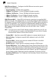
5 System Configuration Service Settings DHCP The wireless AP/Router includes a Dynamic Host Configuration Protocol (DHCP) server that can assign temporary IP addresses to any attached host requesting the service. The unit can support up to 253 local clients. Addresses are assigned to clients from a common address pool configured on the unit. Configure an address pool by specifying start and end IP addresses. Be sure not to include the unit's IP address in the address pool range.
5 Service Settings - MAC: The physical layer address used to uniquely identify the static IP address to be assigned to the specified client MAC address. The IP address must be in the same subnet as the wireless AP/Router.. - IP: The static IP address to be assigned to the specified client MAC address. The IP address must be in the same subnet as the wireless AP/Router. - Description: An optional brief description that can be used to help identify the client device.
5 System Configuration • UPnP Internet Gate Device – Enables UPnP on the wireless AP/Router. (Default: Disabled) • Save – Saves the enabled UPnP configuration. • Cancel – Restores the previous UPnP configuration information. UPnP Map — Displays UPnP statistics. • Remote Host – Displays the UPnP host device on the WAN. • External Port – Displays the external WAN port from which UPnP discovery is broadcast to the wireless AP/Router. • Internal Client – Displays the LAN connected UPnP supporting device.
5 Service Settings • DDNS – Enables DDNS. (Default: Disabled) • DDNS Server Type – Specifies the DDNS service provider, DynDns.org, Non-IP.com, or ZoneEdit.com. (Default: DynDns.org) • DDNS Username – Specifies your username for the DDNS service. • DDNS Password – Specifies your password for the DDNS service. • Confirmed Password – Prompts you to re-enter your chosen password. • Hostname to register – Specifies the prefix to identify your presence on the DDNS server.
5 System Configuration • Log Level – Configures the minimum severity level for event logging. The system allows you to limit the messages that are logged by specifying the minimum severity level. (Default: 4 Warning) - 1 Alert – An error condition requiring immediate user intervention to prevent a problem. - 2 Critical – An error condition that may require user intervention. - 3 Error – An error condition that does not cause significant problems with normal operation.
5 Service Settings Date and Time Settings The Date/Time page allows you to manually configure time settings or enable the use of an NTP server. Figure 5-36. Date and Time Settings - NTP • Date Time Set By – Allows you to manually configure time settings or select the use of an NTP server. • Time Zone – Specifies the time zone in Greenwich Mean Time (GMT). • Daylight Saving – Enables daylight savings for summertime. Daylight Saving Time begins for most of the United States at 2:00 a.m.
5 System Configuration Figure 5-37. Date and Time Settings - Manual • Date Time Set By – Allows you to manually configure time settings or select the use of an NTP server. • Time Zone – Specifies the time zone in Greenwich Mean Time (GMT). • Daylight Saving – Enables daylight savings for summertime. (Default: Disabled) • Date Value Setting – Sets the date for the wireless AP/Router in year; month; day format. • Time Value Setting – Sets the time for the wireless AP/Router in hour, minute; second format.
5 Service Settings PING Test The wireless AP/Router provides the function of “pinging” a specified IP address or URL to test for connectivity. Figure 5-38. Ping Test - success Figure 5-39. Ping Test - failure • PING Destination – The destination IP address to test. • PING – Sends the request.
5 System Configuration Management Settings The wireless AP/Router’s Management Settings menu provides the same configuration options in both Router and AP Mode. These settings allow you to change the operating mode, set the system time, configure a management access password, and upgrade the system software. Admin Accounts and Remote Administration Management access to the wireless AP/Router is controlled through different levels of user name and password.
5 Management Settings Admin Accounts — Configures access levels, usernames and passwords. (Maximum 32 entries are allowed.) • Access Level – Configures the access privileges that the user has. - Admin: Grants administrator level access, no restrictions. - User: Grants user level access, some restrictions. - Guest: Grants guest level access, configuration settings may not be changed.
5 System Configuration Config Settings The Config Setting page allows you to save the wireless AP/Router’s current configuration or restore a previously saved configuration back to the device Figure 5-41. Config Settings • Save – Saves the current configuration locally. • Restore – Restores a previously saved configuration from a specified file. • Factory Default – Restores the factory defaults. • View Current Config – Opens a display window that details parameters about the current configuration.
5 Management Settings Firmware Upgrade You can update the wireless AP/Router firmware by using the Firmware Update facility. Figure 5-43. View Current Config Settings Firmware Update — Allows you to upload new firmware manually by specifying a file path. Make sure the firmware you want to use is on the local computer by clicking Browse to search for the firmware to be used for the update. • Browse – Opens a directory on the local hard drive for specifying the path of file required for uploading.
5 System Configuration Status Information The Information pages display details on the current configuration and status of the wireless AP/Router, including associated wireless stations and event log messages. Note: The Status Information pages will display different statistics depending on the mode selected, AP or Router. Please refer to “Installation” on page 2-1 for details.
5 Status Information Figure 5-45. System Information - WAN Statistics (Router mode) WAN — Displays the basic WAN information: • Ethernet Speed – The connection speed of the WAN port. • Ethernet MAC Address – The physical layer address for the Ethernet WAN port. • IP Assignment – Indicates if the IP address has been manually configured or assigned by DHCP. • DHCP Client – Displays if the wireless AP/Router is acting as a DHCP client.
5 System Configuration • MAC Address – The shared physical layer address for the wireless AP/Router’s LAN ports. • IP Address – The IP address configured on the wireless AP/Router. • Subnet Mask – The mask that identifies the host address bits used for routing to the LAN port. • DHCP Server Function – Indicates the DHCP server status. Figure 5-47.
5 Status Information WDS — Displays the basic WDS information. Note: WDS information only applies to WLAN1. • WDS Mode – The WDS mode in which WLAN1 is set to operate. • WDS Encryption Type – The encryption type used by WLAN1. • WDS MAC List – Displays any entries in the WDS MAC list. (Maximum: 4) Routing Table This page displays the information necessary to forward a packet along the best path toward its destination. Each packet contains information about its origin and destination.
5 System Configuration Figure 5-51. Packet statistics • Interface – Displays the name of the interface the packet statistics relate to. • Recv Bytes – The total number of bytes received on the interface. • Send Bytes – The total number of bytes sent from the interface. • Recv Pkts – The total number of packets received on the interface. • Send Pkts – The total number of packets sent from the interface.
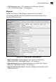
5 Status Information System Logs The wireless AP/Router supports a logging process that controls error messages saved to memory or sent to a Syslog server. The logged messages serve as a valuable tool for isolating wireless AP/Router and network problems. The Events Log page displays the latest messages logged in chronological order, from the newest to the oldest. Log messages saved in the wireless AP/Router’s memory are erased when the device is rebooted. Figure 5-52.
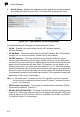
5 System Configuration • Process – Displays system log messages concerned with all other process other than the Linux Kernel, including communication through the wireless AP/Router’s ports. • Refresh – Refreshes the System Log display to display the most recent messages received. • Date Time – The date and time of receival of the system log message. • Facility Priority – The priority level of the system log message. • Category – The category of system log message.
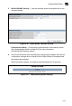
Appendix A: Troubleshooting Check the following items before you contact local Technical Support. 1. If wireless clients cannot access the network, check the following: • Be sure the access point and the wireless clients are configured with the same Service Set ID (SSID). • If authentication or encryption are enabled, ensure that the wireless clients are properly configured with the appropriate authentication or encryption keys. 2.
A Troubleshooting Diagnosing LED Indicators Troubleshooting Chart Symptom Action POWER LED is Off • The AC power adapter may be disconnected. Check connections between the wireless AP/Router, the power adapter, and the wall outlet. WLAN LED is Off • The wireless AP/Router’s radio has been disabled through it’s web management interface. Access the management interface using a web browser to enable the radio.
Appendix B: Specifications Operating Frequency 802.11g/n: 2.4 ~ 2.4835 GHz (US, Canada) 2.4 ~ 2.4835 GHz (ETSI, Japan) 2.412 ~ 2.462 GHz (Taiwan) 802.11b: 2.4 ~ 2.4835 GHz (US, Canada) 2.4 ~ 2.4835 GHz (ETSI) 2.4 ~ 2.497 GHz (Japan) 2.412 ~ 2.462 GHz (Taiwan) Data Rate 802.11b: 1, 2, 5.5, 11 Mbps per channel 802.11g: 6, 9, 12, 18, 24, 36, 48, 54 Mbps per channel 802.11n: 27, 54, 81, 108, 162, 216, 243, 270, 300 Mbps per channel (40MHz) Operating Channels 802.11b/g and 802.11n (20MHz): 11 channels 802.
B Specifications EN 55022B EN 55024 EN61000-3-2 EN61000-3-3 Radio Signal Certification FCC Part 15C 15.247, 15.207 (2.4 GHz) EN 300 328 EN 301 489-1 EN 301 489-17 Standards IEEE 802.11b/g IEEE 802.11n draft v2.0 Physical Size 21.0 x 16.5 x 4.0 cm (8.27 x 6.50 x 1.57 in) Weight 350 g (12.
Appendix C: License Information This product includes copyrighted third-party software subject to the terms of the GNU General Public License (GPL), GNU Lesser General Public License (LGPL), or other related free software licenses. The GPL code used in this product is distributed WITHOUT ANY WARRANTY and is subject to the copyrights of one or more authors. For details, refer to the section "The GNU General Public License" below, or refer to the applicable license as included in the source-code archive.
C License Information We protect your rights with two steps: (1) copyright the software, and (2) offer you this license which gives you legal permission to copy, distribute and/or modify the software. Also, for each author's protection and ours, we want to make certain that everyone understands that there is no warranty for this free software.
The GNU General Public License C a). You must cause the modified files to carry prominent notices stating that you changed the files and the date of any change. b). You must cause any work that you distribute or publish, that in whole or in part contains or is derived from the Program or any part thereof, to be licensed as a whole at no charge to all third parties under the terms of this License. c).
C License Information c). Accompany it with the information you received as to the offer to distribute corresponding source code. (This alternative is allowed only for noncommercial distribution and only if you received the program in object code or executable form with such an offer, in accord with Subsection b above.) The source code for a work means the preferred form of the work for making modifications to it.
The GNU General Public License C consequence you may not distribute the Program at all. For example, if a patent license would not permit royalty-free redistribution of the Program by all those who receive copies directly or indirectly through you, then the only way you could satisfy both it and this License would be to refrain entirely from distribution of the Program.
C License Information NO WARRANTY 1. BECAUSE THE PROGRAM IS LICENSED FREE OF CHARGE, THERE IS NO WARRANTY FOR THE PROGRAM, TO THE EXTENT PERMITTED BY APPLICABLE LAW. EXCEPT WHEN OTHERWISE STATED IN WRITING THE COPYRIGHT HOLDERS AND/OR OTHER PARTIES PROVIDE THE PROGRAM "AS IS" WITHOUT WARRANTY OF ANY KIND, EITHER EXPRESSED OR IMPLIED, INCLUDING, BUT NOT LIMITED TO, THE IMPLIED WARRANTIES OF MERCHANTABILITY AND FITNESS FOR A PARTICULAR PURPOSE.
Glossary 10BASE-T IEEE 802.3-2005 specification for 10 Mbps Ethernet over two pairs of Category 3 or better UTP cable. 100BASE-TX IEEE 802.3-2005 specification for 100 Mbps Fast Ethernet over two pairs of Category 5 or better UTP cable. Access Point An internetworking device that seamlessly connects wired and wireless networks. Access points attached to a wired network, support the creation of multiple radio cells that enable roaming throughout a facility.
Glossary Encryption Data passing between the access point and clients can use encryption to protect from interception and evesdropping. Ethernet A popular local area data communications network, which accepts transmission from computers and terminals. File Transfer Protocol (FTP) A TCP/IP protocol used for file transfer. Hypertext Transfer Protocol (HTTP) HTTP is a standard used to transmit and receive all data over the World Wide Web. IEEE 802.
Glossary Open System A security option which broadcasts a beacon signal including the access point’s configured SSID. Wireless clients can read the SSID from the beacon, and automatically reset their SSID to allow immediate connection to the nearest access point. Orthogonal Frequency Division Multiplexing (ODFM) OFDM allows multiple users to transmit in an allocated band by dividing the bandwidth into many narrow bandwidth carriers.
Glossary Virtual Access Point (VAP) Virtual AP technology multiplies the number of Access Points present within the RF footprint of a single physical access device. With Virtual AP technology, WLAN users within the device’s footprint can associate with what appears to be different access points and their associated network services. All the services are delivered using a single radio channel, enabling Virtual AP technology to optimize the use of limited WLAN radio spectrum.
Index A I AC power adapter 1-5 ACL configuration 5-35 administrator accounts 5-60 administrator password 5-60 administrator username 5-60 Advanced Setting menu 5-23 AES 5-29, 5-33 AP mode 2-1, 2-2 authentication mode 4-12, 5-28, 5-33 IEEE 802.11n 1-1 IEEE 802.
Index software displaying version 5-54 static IP 4-5, 5-7 subnet mask 4-5, 5-5, 5-17, 5-64 system Information 5-63 system log 5-68 T time zone 5-56 TKIP 5-29, 5-33 troubleshooting A-1, C-1 U UPnP 5-52 URL filter 5-49 URLs 5-49 Index-2 V virtual server mapping 5-45 W WAN packet filter 5-47 WAN setting 5-5 WDS MAC list 5-34 WDS settings 5-32 WEP 5-25, 5-28, 5-29, 5-33 WLAN setting 4-11, 5-21 WPA/WPA2 5-25, 5-28 WPS 5-37 WPS button 1-5 WPS, PBC 5-39 WPS, PIN 5-38
TECHNICAL SUPPORT From U.S.A. and Canada (24 hours a day, 7 days a week) Phn: 800-SMC-4-YOU / 949-679-8000 Fax: 949-502-3400 ENGLISH Technical Support information available at www.smc.com FRENCH Informations Support Technique sur www.smc.com DEUTSCH Technischer Support und weitere Information unter www.smc.com SPANISH En www.smc.com Ud. podrá encontrar la información relativa a servicios de soporte técnico DUTCH Technische ondersteuningsinformatie beschikbaar op www.smc.