CheetahSwitch Workgroup-3726M Quick Installation Guide
Quick Installation Guide CheetahSwitch Workgroup-3726M Intelligent/Stackable Fast Ethernet Switch with 24 10BASE-T / 100BASE-TX (RJ-45) Ports, and Optional Media Expansion and Stack Modules
Copyright © 2002 by Accton Technology Corporation. All rights reserved. No part of this document may be copied or reproduced in any form or by any means without the prior written consent of Accton Technology Corporation. Accton makes no warranties with respect to this documentation and disclaims any implied warranties of merchantability, quality, or fitness for any particular purpose. The information in this document is subject to change without notice.
Limited Warranty Accton Technology Corporation Limited Warranty: Accton warrants all is products to be free of manufacturing defects in workmanship and materials, under normal use and service, for the applicable warranty term. All Accton products carry a standard 90-day limited warranty from the date of purchase from Accton or its Authorized Reseller.
Limited Warranty LIABLE UNDER THIS WARRANTY IF ITS TESTING AND EXAMINATION DISCLOSE THE ALLEGED DEFECT IN THE PRODUCT DOES NOT EXIST OR WAS CAUSED BY CUSTOMER'S OR ANY THIRD PERSON'S MISUSE, NEGLECT, IMPROPER INSTALLATION OR TESTING, UNAUTHORIZED ATTEMPTS TO REPAIR, OR ANY OTHER CAUSE BEYOND THE RANGE OF THE INTENDED USE, OR BY ACCIDENT, FIRE, LIGHTNING, OR OTHER HAZARD.
Contents Introduction 1 Installing the Switch Package Contents Description of Hardware Mounting the Switch Stacking Switches on a Flat Surface Mounting Switches in a Rack Installing a Management Module Installing Optional Media and Stacking Modules Connecting to the Stack’s Backplane Connecting the Switch System Making a Connection to an RJ-45 Port Connecting to a 100BASE-FX Port Connecting to a Gigabit Fiber Optic Port Powering On the Switch Verifying Port Status Verifying System Operation Applications
Contents Canada Department of Communications - Class A BSMI Class A (Taiwan) VCCI Class A Compliance (Japan) CE Mark Declaration of Conformance for EMI and Safety (EEC) 16 16 16 17 Safety Compliance Warning: Fiber Optic Port Safety Avertissment: Ports pour fibres optiques - sécurité sur le plan optique Warnhinweis: Faseroptikanschlüsse - Optische Sicherheit Underwriters Laboratories Inc.
Introduction The CheetahSwitch Workgroup-3726M is perfect for moving workgroups from conventional 10 Mbps Ethernet to multiple-segment 100 Mbps Fast Ethernet, and for consolidating your network equipment into a single, clean, efficient, and super-fast switch stack. This switch system delivers dedicated 100 Mbps links to each attached LAN segment (independent collision domain) or to any PC attached directly to the stack – all with conventional cabling and adapters.
Quick Installation Guide Installing the Switch Before installing the switch verify that you have all the items listed under “Package Contents.” If any of the items are missing or damaged, contact your local Accton distributor. Also be sure you have all the necessary tools and cabling before installing the switch. Note that this switch can be installed on any suitably large flat surface or in a standard EIA 19-inch rack.
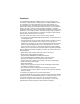
Installing the Switch The following figure shows the components of this switch system: 10/100 Mbps RJ-45 Ports Port Status Indicators Module Indicators System Indicators Mode Selection 1 100-240V~ 50-60Hz 2A DC INPUT V 3.3 5 12 Power Socket A 15 3 0.7 RPU Connector Media or Stacking Module Slot Media Module Slot Management Module Slot Mounting the Switch This switch can be placed directly on your desktop, or mounted in a rack.
Quick Installation Guide Mounting Switches in a Rack Please comply with the following instructions to ensure that your switch is securely mounted in the rack. 1. Use a standard EIA 19-inch rack. 2. Use the brackets and screws supplied in the rack mounting kit. Use a cross-head screwdriver to attach the brackets to the side of the switch.
Installing the Switch You can install a module as described below: 1. Disconnect power to the switch (the modules are not hot-swappable). 2. Remove the face plate on the appropriate slot by removing the two screws with a flat-head screwdriver. 3. Before opening the package that contains the module, touch the bag to the switch casing to discharge any potential static electricity. 4. Remove the module from the anti-static shielded bag. 5.
Quick Installation Guide Connecting the Switch System The CheetahSwitch Workgroup-3726M provides 24 RJ-45 ports on the base unit. Each of these ports supports a connection to 10 Mbps Ethernet or 100 Mbps Fast Ethernet, and supports full or half-duplex operation. The transmission speed for each port is automatically set by the switch to match the highest speed supported by the connected device. The transmission mode can be set for each port using auto-negotiation (if also supported by the attached device).
Installing the Switch switches break up the path for connected devices into separate collision domains, you should not include the switch or connected cabling in your calculations for cascade length involving other devices. Connecting to a 100BASE-FX Port If you connect fiber cable to the 100BASE-FX module, be sure you use an SC-type connector. When inserting the cable, be sure the tab on the plug clicks into position to ensure that it is properly seated.
Quick Installation Guide 1000BASE-SX and 1000BASE-LX fiber optic cable depends on the core size and the rating of the cable, as shown in the following tables. Maximum 1000BASE-SX Gigabit Ethernet Cable Length Fiber Size Fiber Bandwidth Maximum Cable Length 62.
Installing the Switch Verifying Port Status Check each connection by viewing the port indicators on the base unit front panel. Their staus is shown in the following table. LED System Power RDP Mgmt RJ-45 Ports Link Activity* FDX* FC* Module Ports Status Activity S tate Indication On On On Switch is receiving power. Redundant power unit on. Management agent operational. On Yellow Green Flashing On On On Port has established a valid network connection. Communications have been set to 10 Mbps.
Quick Installation Guide • See if your cable is functioning properly by using it for another port and attached device that displays valid indications when connected to the network. • Be sure no twisted-pair cable exceeds 100 meters (328 feet). 100 Mbps fiber cable should be under 2 kilometers (1.24 miles). The maximum length for fiber optic Gigabit connections is listed in the table on the preceding page.
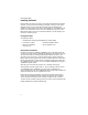
Product Specifications Printers 1 1 Servers 1 Switch at remote site (via fiber link) 1 CheetahSwitch Stack 10M Hub Stack Collapsed Backbone (via Gigabit link) 100M Hub Stack ... ... Product Specifications Base Unit Physical Characteristics Access Method Standards Conformance Communication Rate Communication Mode Media Supported Number of Ports Indicator Panel Dimensions Weight Input Power Maximum Current Power Consumption Heat Dissipation CSMA/CD IEEE 802.3, IEEE 802.
Quick Installation Guide Temperature Humidity Certification Emissions Immunity Safety Operating: 0~50 °C / 32~122 °F Storage: -40~70 °C / -40~158 °F 5% to 95% (noncondensing) CE Mark FCC Class A, VCCI Class A, CISPR Class A, EN 61000-3-2/3 IEC 61000-4-2/3/4/5/6/11 CSA/NRTL, TÜV/GS Switching Criteria Network Bridging Function Switching Method Address Table Queue Buffer Address Resolution Filtering, forwarding and learning Store-and-forward 8K entries total 128K bytes per 10/100 Mbps port 2M bytes for 1000
Troubleshooting 1000BASE-SX Module (EM4582-SX-SC) Access Method Standards Conformance Communication Rate Communication Mode Media Supported Output Power Receiver Sensitivity Power Budget Number of Ports Indicator Panel CSMA/CD IEEE 802.3z 1000 Mbps Full or half duplex 50/125 micron or 62.5/125 micron multimode fiber Minimum: -9.
Quick Installation Guide Cause Solution Power indicator does not light up after power on. Symptom Power outlet, power cord, or internal power supply may be defective. Check the power outlet by plugging in another device that is functioning properly. Check the power cord with another device. If these measures fail to resolve the problem, contact your Accton distributor. Link indicator does not light up after making a connection. Network interface (e.g.
Port and Cable Assignments Port and Cable Assignments RJ-45 Port Description RJ-45 station ports (MDI-X) can be attached to any devices that use a standard network interface (e.g., a workstation, server, bridge or router). RJ-45 daisy-chain ports (MDI) can be cascaded to a station port on similar networking devices (e.g., another switch or hub).
Quick Installation Guide EMI Certification FCC Class A Certification (USA) Warning: This equipment generates, uses, and can radiate radio frequency energy and, if not installed and used in accordance with the instruction manual, may cause interference to radio communications.
EMI Certification CE Mark Declaration of Conformance for EMI and Safety (EEC) This information technology equipment complies with the requirements of the Council Directive 89/336/EEC on the Approximation of the laws of the Member States relating to Electromagnetic Compatibility and 73/23/EEC for electrical equipment used within certain voltage limits and the Amendment Directive 93/68/EEC.
Quick Installation Guide Safety Compliance Warning: Fiber Optic Port Safety When using a fiber optic media expansion module, never look at the transmit laser while it is powered on. Also, never look directly at the fiber TX port and fiber cable ends when they are powered on. Avertissment: Ports pour fibres optiques sécurité sur le plan optique Ne regardez jamais le laser tant qu’il est sous tension.
Safety Compliance Wichtige Sicherheitshinweise (Germany) 1. 2. 3. Bitte lesen Sie diese Hinweise sorgfältig durch. Heben Sie diese Anleitung für den späteren Gebrauch auf. Vor jedem Reinigen ist das Gerät vom Stromnetz zu trennen. Verwenden Sie keine Flüssigoder Aerosolreiniger. Am besten eignet sich ein angefeuchtetes Tuch zur Reinigung. 4. Die Netzanschlu ßsteckdose soll nahe dem Gerät angebracht und leicht zugänglich sein. 5. Das Gerät ist vor Feuchtigkeit zu schützen. 6.
Quick Installation Guide Optional Hardware Modules AC-ES3726M-AGENT: EM3582-FX-SC: EM4582-SX-SC: EM4582-LX-SC: EM3580-STACK: RPU150W: ST5002: 20 SNMP/RMON Management Module with RS-232 Port Media Module with 2 100BASE-FX (SC-type) Ports Media Module with 1 1000BASE-SX (SC-type) Port Media Module with 1 1000BASE-LX (SC-type) Port Stacking Module kit including 30 cm stacking cable Redundant Power Supply SC to ST Plug Converter for Fiber Optic Module (for 62.
AC-ES3726M E012002-R01 F2.