
User's Manual


11
AT308 - USER MANUAL
30.00
NOT RELEASED
PRELIMINARY
NOT CHECKED
STATED)
The recipient acknowledges that the copyright & design right in this drawing belong to & remains
(AND SIZE)
CERT'D
CHECKED
DRAWN/DATE
FINISH
MATERIAL
MASS
ESTIMATED
vested in ACCURACY INTERNATIONAL LTD. No license is given by ACCURACY INTERNATIONAL LTD
CH'NGE
STATED)
OTHERWISE
SCALE
DIM'N IN
TITLE
ORIGINAL
CHANGE:
C
RESPONSIBLE AUTHORITY AND
DRAWING NUMBER
LAST
3
0
20 50 100
(UNLESS
A
15'
.00 ± 0.1
.0 ± 0.25
UNIT ± 0.5
Projection
3rd Angle
ANG ±0
TOLS:
L
(3) REFERENCES TO STANDARDS & SPECS. IMPLY LATEST ISSUE.
mm
ACCURACY INTERNATIONAL
1
CORNERS OF BLIND HOLES, RECESSES & STEPS.
(2) A RADIUS OR CHAMFER OF 0.2 (MAX) IS PERMITTED IN THE
OF
1
ARE INSPECTION DIMENSIONS
DIMENSIONS DISPLAYED THUS
SH'T
(1) ALL BURRS & SHARP EDGES TO BE REMOVED.
DRAWING PROCEDURE TO DEF. STAN. 05-10 AND/OR BS 8888.
WHERE A THREAD DEPTH IS QUOTED, IT IS MINIMUM FULL THREAD DEPTH.
(6) UNLESS OTHERWISE STATED, ALL TAPPED HOLE THREAD FORMS ARE TO BS 3643-6H.
(WHERE NUMBER IN BOX IS APPLICABLE CHANGE)
(5) DRAWING FEATURES MARKED THUS 3 INDICATE LATEST ISSUE MODIFICATION.
(4) ALL DIMENSIONS ARE FINISHED DIM'NS. i.e. AFTER APPLICATION OF SURFACE FINISH
The recipient shall maintain the confidentiality of the drawing.
g
1:10
AT, GENERAL ASSY (FOLDING)
NATO STOCK No:
ISSUE
AI-26677
for the recipient to copy or make use of the information contained in thisdrawing.
DATE:
BY:
SPECIFICATION
SPECIFICATION
1 2 3 4 5 6 7 8 9 10
A
B
C
D
E
F
G
H
J
K
This drawing contains confidential information belonging to ACCURACY INTERNATIONAL LIMITED.
SURFACE ROUGHNESS
(UNLESS
OTHERWISE
N7
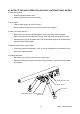
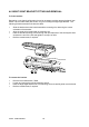
4.1 BIPOD FITTING AND OPERATION (ACCURACY INTERNATIONAL MODEL)
To remove the bipod:
Operate the bipod release catch.
Pull the bipod forward out of its mounting.
To fit the bipod:
Offer the bipod spigot up to the mounting.
Push the bipod into the mounting until the release catch engages.
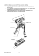
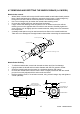
To deploy and adjust the legs:
Rotate each leg round through 90 degrees until the leg locking button engages.
Depress the leg catch to deploy the inner leg, while supporting the weight of the rifle.
Alternatively the leg can be pulled down to find the desired height once the first locking
position has been disengaged.
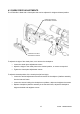
To adjust the bipod tilt or ‘Cant’ tension:
The tension/resistance against the ‘cant ‘or ‘loll’ can be tightened or loosened by using
the tension adjustment knob.
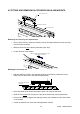
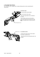
To collapse the bipod:
Depress the leg catch and push the inner leg(s) fully in.
Depress the leg locking button and rotate the leg forwards or rearwards until the detent
pin engages.
TENSION
ADJUSTMENT KNOB
BIPOD RELEASE CATCH
LEG CATCH
LEG LOCKING
BUTTON
BIPOD SPIGOT