
User's Manual


21
AT308 - USER MANUAL
6. FIELD STRIPPING THE RIFLE
Before stripping the rifle, carry out the safety precautions as described in section 1.4.
To field strip the rifle:
Depress the magazine catch and remove the magazine (if fitted).
Cover the lenses of the telescopic sight.
Remove the sling (if fitted)
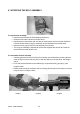
FOLDING CHASSIS MODEL: Partially fold the rear frame to allow the bolt to be
removed as shown below.
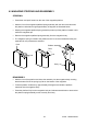
FIXED CHASSIS MODEL: Loosen the cheek piece retaining screws and remove the
cheek piece as described in section 4.3.
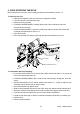
Open the bolt fully.
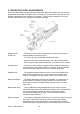
Press and hold the bolt release catch and slide the bolt rearwards to remove.
To reassemble after field stripping:
Ensure the serial numbers on the Action Body, Bolts and Shroud match, if not, report the
issue to the appropriate authority.
FOLDING CHASSIS MODEL ONLY: Fold the rear frame through 45 degrees, as shown
above.
With the bolt assembly in the ‘cocked’ position (see section 6.1 - image 3), align the bolt
assembly with the action body as shown above.
Press and hold the bolt release catch.
Slide the bolt assembly half way into the action body and release the bolt release catch.
Attempt to rotate the bolt slightly left and right until the bolt engages with the bolt stop.
Cycle the bolt fully several times to ensure correct fitment & operation.
Unfold the rear fame fully or refit the cheek piece assembly depending on chassis type.
Refit the sling.
Refit an empty magazine.
30.00
NOT RELEASED
PRELIMINARY
NOT CHECKED
STATED)
vested in ACCURACY INTERNATIONAL LTD. No license is given by ACCURACY INTERNATIONAL LTD
(AND SIZE)
CERT'D
CHECKED
DRAWN/DATE
FINISH
MATERIAL
MASS
ESTIMATED
for the recipient to copy or make use of the information contained in thisdrawing.
CH'NGE
STATED)
OTHERWISE
SCALE
DIM'N IN
TITLE
ORIGINAL
CHANGE:
C
RESPONSIBLE AUTHORITY AND
DRAWING NUMBER
LAST
3
0
20 50 100
(UNLESS
A
15'
.00 ± 0.1
.0 ± 0.25
UNIT ± 0.5
Projection
3rd Angle
ANG ±0
TOLS:
L
(3) REFERENCES TO STANDARDS & SPECS. IMPLY LATEST ISSUE.
mm
ACCURACY INTERNATIONAL
1
CORNERS OF BLIND HOLES, RECESSES & STEPS.
(2) A RADIUS OR CHAMFER OF 0.2 (MAX) IS PERMITTED IN THE
OF 1
ARE INSPECTION DIMENSIONS
DIMENSIONS DISPLAYED THUS
SH'T
(1) ALL BURRS & SHARP EDGES TO BE REMOVED.
DRAWING PROCEDURE TO DEF. STAN. 05-10 AND/OR BS 8888.
WHERE A THREAD DEPTH IS QUOTED, IT IS MINIMUM FULL THREAD DEPTH.
(6) UNLESS OTHERWISE STATED, ALL TAPPED HOLE THREAD FORMS ARE TO BS 3643-6H.
(WHERE NUMBER IN BOX IS APPLICABLE CHANGE)
(5) DRAWING FEATURES MARKED THUS 3 INDICATE LATEST ISSUE MODIFICATION.
(4) ALL DIMENSIONS ARE FINISHED DIM'NS. i.e. AFTER APPLICATION OF SURFACE FINISH
The recipient shall maintain the confidentiality of the drawing.
g
AT, GENERAL ASSY (FOLDING)
NATO STOCK No:
ISSUE
AI-26677
1:1
DATE:
BY:
SPECIFICATION
SPECIFICATION
1 2 3 4 5 6 7 8 9 10
A
B
C
D
E
F
G
H
J
K
This drawing contains confidential information belonging to ACCURACY INTERNATIONAL LIMITED.
The recipient acknowledges that the copyright & design right in this drawing belong to & remains
SURFACE ROUGHNESS
(UNLESS
OTHERWISE
N7
BOLT RELEASE CATCH
BOLT STOP