MODEL AW SNIPER 7.62 x 51 SNIPER RIFLE USERS MANUAL Accuracy International Limited P.O. Box 81 Portsmouth Hampshire, England PO3 5SJ Telephone: +44 (023) 9267 1225 Fax: +44 (023) 9269 1852 E-mail: precision@accint.org VAT No. GB 430-6893-46 BS EN ISO 9001 (1994) NATO Supplier No: U 4393 PDF created with FinePrint pdfFactory trial version www.pdffactory.
TABLE OF CONTENTS PARA CONTENTS PAGE Table of Contents Technical Specification Introduction General Description Safety Features Safe Handling instructions Operating Instructions 1 3 5 5 5 7 7 1 Safety Precautions 7 2 2A A1 A2 A3 A4 2B 2C 2D 2E 2F 2G 2H 2I 2J 2K 2L 2M 2N 2O Assembling and Stripping the Rifle Assembling Bipod Sight/Mount Bolt Magazine Setting up the Rifle Loading Firing and operating the Bolt Reloading Unloading To Unload a live Cartridge Zeroing the Rifle Zeroing Check List Field St
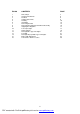
FIG NO CONTENTS PAGE 1 2 3 4 5 6 7 8 9 10 11 12 13 14 15 16 Rifle, Sniper Safe/Fire Mechanism The Bolt Setting Up the Rifle Loading Unloading Removing the Bolt Removing the Firing Pin and Shroud Assembly Stripping the Magazine Telescopic Sight Reticle Pattern Rearsight Disc Type Iron Sights Foresight Rearsight ‘flip up’ Blade Type Iron Sights Butt Length Adjustment Transit Case and Accessories 3 6 9 9 10 12 15 16 17 17 19 21 21 22 23 29 2 PDF created with FinePrint pdfFactory trial version www.
Fig 1 Rifle, Sniper TECHNICAL SPECIFICATION Calibres: 7.62 x 51 NATO (.308 Win) Weight: AW = 5.9 kg (13.0 lb) including magazine, handstop and telescopic sight mount with 3-12x50 Schmidt und Bender telescopic sight AWP = 6.5 kg (14.3 lb), spec as above Overall Length: AW 1178mm (46.4”) two butt spacers fitted AWP 1120mm (44”) two butt spacers fitted Action: Front locking, 3 lugs, integral sight rail, machined from solid ordnance steel bar Bolt: 60 degrees opening, 6mm (0.24”) striker fall.
Trigger: 2 stage, adjustable, set at 1.8 kg (4lbs) NOTE: Mechanisms optimised against dirt and ice Barrel: Stainless matchgrade, 1-10, 11 & 12 twist. AW 26” with muzzle brake, AWP 24” long Safety: 3 way ‘safe’ blocks the firing pin and locks bolt in closed position. Middle position ‘safe’ blocks the firing pin, but bolt can be manipulated.
INTRODUCTION USERS: YOU MUST READ THIS MANUAL BEFORE USING THE RIFLE AND EQUIPMENT DESCRIBED THE ACCURACY INTERNATIONAL MODEL AW / AWP SNIPER RIFLE is Accuracy International’s (AI’s) second generation sniper rifle and is the culmination of 10 years development. Uniquely, the ‘AW’ system and the PM / L96 before it, are ongoing developments of a completely fresh approach to the sniper’s rifle.
SAFETY FEATURES The AW sniper rifle bolt has three forward locking lugs and one emergency lug at the rear. The firing pin cannot protrude from the front of the bolt face unless the bolt handle is in the fully closed position. Gas leakage from the rear of the action body is minimised by a tight fitting bolt, an action body with very few ports and bolt shroud at the rear to deflect any gases that get this far, away from the firers face.
SAFE HANDLING INSTRUCTION 1. Always Check the rifle is unloaded when first handling your own (or another persons rifle), by opening the bolt and physically inspecting the chamber and magazine. 2. Always have the rifle’s bolt open or removed when it is being carried, or when it is between exercises. 3. Before firing the rifle, always remove the bolt and check the bore is not obstructed. 4.
2. ASSEMBLING AND STRIPPING THE RIFLE 2A Assembling Rifles are normally delivered to customers complete in their transit case in which instance he stripping instructions should be read before the assembly instructions. If, however, the rifles are broken down for transport without a transit case then the following instructions should be followed: A1 Bipod Fit the bipod by inserting the spigot on the bipod into the socket at the front of the rifle forend.
If the shroud is loose and the nib is at the bottom of the cocking cam, take the bolt body in the left hand and with the left thumb depress the bolt location pin. With the right hand holding the shroud, rotate the shroud 60 degrees clockwise until the cocking piece slides up the cam and locates in the indent at the top of the cam – with an audible click (it can be easily felt). The bolt is now ready for placement in the rifle.
B5 Check and if necessary adjust the position of the telescopic sight to obtain the correct eye relief (factory set whenever possible). B6 Adjust the butt length by adding or subtracting butt spacers to suit the size of the firer. FIRING THE RIFLE CAUTION: 2C Before firing the rifle ensure that solvent, oil or grease has been removed from the bore. Always use a rod or pull through from the receiver end to avoid damage to muzzle. Use the rod and rod guide whenever possible.
NOTE: If the magazine is over loaded, it will be difficult to get the magazine to engage with the bolt closed and to strip off the first round. The rear end of the firing pin protrudes through the rear of the bolt shroud to act as a cocking indicator when the action is cocked (primed). C5 2D APPLY THE SAFETY CATCH IF NECESSARY Firing and Operating the Bolt – Sequence of Operations The following sequence will be of assistance when firing and operating the rifle.
2E 2F Reloading – to reload the rifle E1 Remove the empty magazine by depressing the release catch and pulling the magazine out with the fingers. E2 Insert a fresh magazine with the same hand and push home until catch engages (audible click). E3 Close the bolt chambering a new cartridge. E4 Apply safety catch. E5 The rifle is now reloaded and ready to engage a new target. Unloading – To unload the rifle (Fig 6) FIG 6.
G3 Position hand to catch ejected round. G4 Cycle bolt to unload chamber. G5 Look or feel to ensure the chamber is empty. G6 Leave bolt open or remove completely. If weapon is to be put away: 2H G7 With the safety catch in the FIRE position, hold the trigger pressed and close the bolt. G8 Place the rifle in its transit / carrying case. G9 EMPTY magazine and insert into the slot provided in the transit case. G10 Store ammunition separately from the rifle and its case.
2I H7 On completion of zeroing, take note of the reading on the adjustment drums. Whilst holding the drums firmly between the fingers, loosen the locking caps using a suitable tool in the other hand. H8 Raise and rotate the drums to zero and re-tighten locking caps or lock screws. The rifle is now zeroed. H9 Check if necessary by firing another group.
2J Field Stripping (Fig 7) FIG 7. REMOVING THE BOLT Before stripping the rifle carry out the safety precautions detailed in paragraph 1. To strip the rifle proceed as follows: 2K J1 Ensure that the lens caps are fitted to the telescopic sight, if supplied. J2 Remove the sling if fitted. J3 Depress the magazine catch and remove the magazine. J4 Raise the bolt handle and slide the bolt rearward. J5 Depress the bolt catch and remove the bolt.
2L To Strip the Bolt (Fig 8) FIG 8. REMOVING THE FIRING PIN & SHROUD ASSEMBLY 2M L1 With the bolt in the receiver body, close the bolt in the cocked position. L2 Apply safety catch to FIRST SAFE position. L3 Open bolt, withdraw and remove from gun. L4 Grasp the bolt and shroud as shown in Fig 8. L5 Depress the bolt location pin with left thumb and turn the shroud clockwise until the shroud and firing pin assembly can be withdrawn. L6 Remove the firing pin and shroud assembly from the bolt.
N4 Remove the platform together with its spring, from the magazine. Replacement is the reverse of the procedure detailed in paragraph N. MAGAZINE PLATFORM MAGAZINE FIG 9. STRIPPING THE MAGAZINE 2O Tests after Re-Assembly O1 Load the magazine with a full load of 10 drill / testing rounds. Check that the lips of the magazine hold each round. O2 Load the magazine into a rifle which is operating correctly. O3 Operate the bolt and check that each round is fed, extracted and ejected correctly. 3.
Eye Relief With the 3-12x50 Schmidt und Bender military sight, the eye relief is set at the factory. Use the method of “setting up the rifle” described in paragraph 2B page 9. Because the head position on the cheekpiece is determined by the open bolt, head position is always the same, so the eye relief is always the same. The only adjustment necessary is to adjust the butt length the suit the size of the firer.
FIG 11. RETICLE PATTERN A range scale is also marked above the click scale on the elevation knob to serve as a check that range has been correctly applied. The top scale can also be used if ranging is required quickly. 3C Technical Details of the AW’s 3-12x50 Sight The reticle shown in Fig 11 is fitted for all police and military rifles, unless otherwise specified. It is an extremely versatile reticle.
ELEVATION DRUM Two types are offered as standard. The elevation drum is calibrated in ½ MOA clicks for police or CT use, with fail safe range indications above the minute scale up to 600m using standard match grade ammunition such as Federal 308M or LAPUA 185gn D45. For long range use up to 1000m, .1 Mil Rad clicks are used with fail safe range indications above the Mil Rad scale calibrated using long range match ammunition such as COOPER HPS or LAPUA B466 (the latter two are supersonic to beyond 1000m).
E4 Set the rearsight – elevation disc to 200m ELEVATION DISC WINDAGE SCREWS (2) FIG 12. REARSIGHT (DISC TYPE) E5 Fire the rifle at a range of 100m (200m) in still conditions and check the position of the mean point of impact (MPI). E6 Adjust the foresight in elevation by screwing the foresight blade adjusting screw in (clockwise) if shooting low, or our (anti-clockwise) if shooting high. E7 Adjust the rearsight for windage by adjusting the screws on each side of the rearsight mount.
The iron sight set should then be removed and placed in their bag ready zeroed. In the event of an emergency when the optical sight is damaged, the optical sight is removed using the universal key and the iron sight set replaced using the same key. The rifle can now be used using the pre-zeroed iron sights.
4.3 Squeeze legs together and put legs in vertical position. 4.4 Pull on feet to extend length of legs to adjust height of rifle. 4.5 Depress catch on each leg to replace inner legs. 4.6 Squeeze legs together to fold away. 4.7 Press catch under forend and pull bipod assembly forward to remove from rifle. 5. BUTT LENGTH ADJUSTMENT – shortening the butt (Fig 15) BUTT SPACERS BUTT PAD SPACERS SECURING SCREWS & WASHERS BUTT PAD FIG 15. BUTT ADJUSTMENT 5.
Cleaning and lubrication before firing Clean the rifle as detailed below and lubricate using a suitable light oil (Breakfree CLP or similar) or leave dry as follows: 6.3 Bore, chamber and barrel exterior – leave dry. 6.4 Bolt – leave face dry, lightly lubricate. 6.5 Action body – lightly lubricate inside surfaces. 6.6 Stock and outer bipod legs – leave dry. 6.7 Bipod inner legs – lightly lubricate. 6.8 Bipod swivel and spigot – lightly lubricate with grease (smear). 6.
7. CARE AFTER FIRING The bore and chamber, together with the gas affected parts should be cleaned, inspected and re-lubricated. 8. INSPECTION At all times after cleaning and before re-lubrication, components and assemblies are to be inspected for serviceability. Any faults or damage should be reported to the relevant authority. 9. CLEANING THE TELESCOPE Cleaning the Telescopic Sight Unit , is restricted to the external surfaces, the object glass and eye lens.
11. USER TIPS 11.1 When using the bipod, always push into the bipod do that on firing the rifle recoils naturally (without resistance) about the ball joint. Pulling back on the bipod can give serious elevation at target, especially on soft ground. 11.2 Press the thumb of the right hand on the top of the action to aid leverage when opening the bolt, to assist the removal of tight extractions. 11.
12. EXTERIOR BALLISTIC DATA CARTRIDGE: BULLET: WEIGHT: RANGE Yd Cooper HPS B476 11gm (170grn) VELOCITY ft/sec TIME OF FLIGHT secs STRIKE ENERGY ft/lb WIND DRIFT in 0 2820 0 3000 0 200 2470 0,227 2300 2.6 400 2135 0,488 1720 11.1 600 1806 0,794 1230 27.4 800 1475 1,160 821 54.5 1000 1200 1,614 541 96.9 CONDITIONS - Sea Level Air pressure 29.53 inches Hg Air Temperature 59 deg F Sidewind 10 mph Below is a table of the approximate exterior ballistic comparisons between 7.
13. TORQUE SETTINGS FOR AW RIFLE Stock side screws Shroud cover screws Muzzle brake clamp Foresight clamp Rearsight clamp Trigger clamp screws Action screws Butt pad screws Scope to action screws 0.8Nm 2.0Nm 4.0Nm 3.5Nm 3.5Nm 3.5Nm 4.0Nm 3.5Nm 4mm key 3mm key Scope ring screws 3.5Nm 2.5Nm 2.5Nm 14.
FIG 16. TRANSIT CASE & ACCESSORIES 1. 2. 3. 4. 5. 6. 7. 8. TRANSIT BOX ROD, CLEANING BRUSH, CLEANING PATCH HOLDER TOOL, UNIVERSAL BOX, CLEANING ROD, CHAMBER GUIDE BOX, FLANNELETTE PATCHES 9. 10. 11. 12. 13. 14. 15. 16. HANDSTOP / SWIVEL MAGAZINE (SPARE) BUTT SPACER 40mm THK BUTT SPACER 10mm THK SCREWS, BUTT, M6 X 100mm LG SLING RIFLE CLEANER / LUB / PRESERVE USERS MANUAL 29 PDF created with FinePrint pdfFactory trial version www.pdffactory.